


 PipePatrol is easy to use
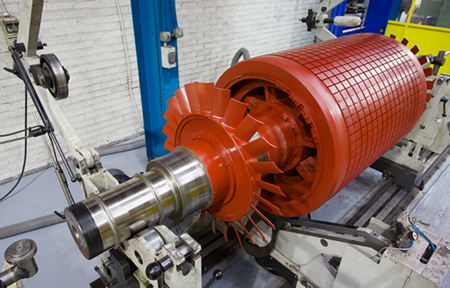
Modern leak detection systems, such as Krohne’s E-RTTM, guarantee reliable leak monitoring for various types and lengths of pipelines
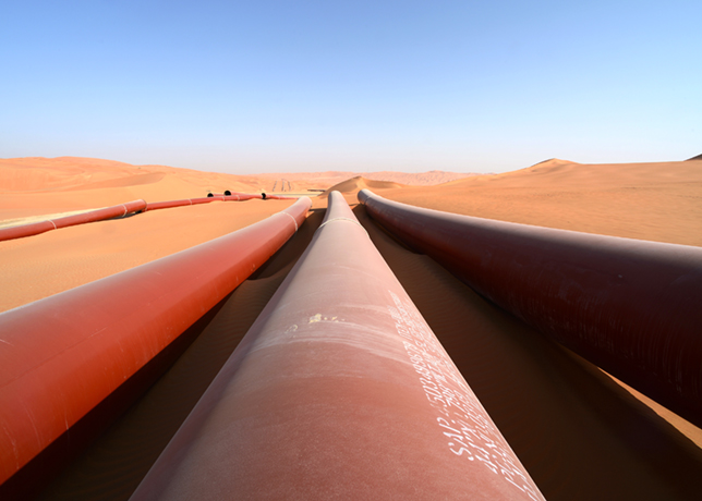
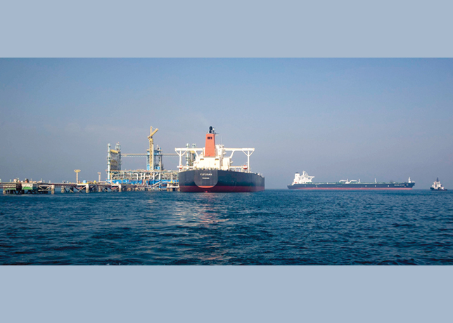
The transportation of fluids in pipelines is increasing all over the world, and for a good reason: Pipelines are among the safest and most economical transportation systems over long routes.
To ensure this cost-effectiveness and safety, both new, and especially existing, pipelines must reflect the standard of the most current technology.
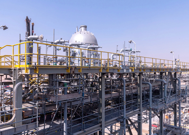
Leaks pose a potential safety risk. They occur for a wide variety of reasons, from earthquakes, corrosion and material failure to drilling by product thieves.
Special leak detection systems (LDS) are often used to limit these risks. In general, leak detection in pipelines refers to the recognition and quick localisation of product leaks.
The reasons to employ leak detection include to minimise the effects of accidents, downtime and product loss, and for regulatory compliance.
Leak detection in pipelines can be performed in various ways, from simple visual controls during inspections to computer-supported systems that monitor conditions, even for underground and undersea pipelines.
REGULATORY FRAMEWORKS
Selecting a suitable leak detection system must meet the needs of the particular application and comply with relevant regulations.
The most important regulations for North America are API RP 1130 and CSA Z662-2011 Annex E.
 |
Figure 1 ... Functional principle of a leak detection system based on E-RTTM |
The API RP (Recommended Practice) 1130 includes a collection of general recommendations for operating leak detection systems, such as clear presentation of the results for the operator and for maintenance.
It also includes performance criteria for selecting a leak detection system, such as:
• Sensitivity: The leak detection system should detect even small leaks within a short period.
• Precision: The leak detection system should locate leaks precisely.
• Robustness: The leak detection system should continue active monitoring despite unsteady or non-ideal conditions.
• Reliability: The leak detection system should not generate false alarms, even though it is highly sensitive.
Separately, the Canadian Standards Association (CSA) Z662 Annex E represents recommended practice for liquid hydrocarbon pipeline system leak detection in Canada.
The CSA Z662 Annex E is the only recommended practice to include precise uncertainties for leak detection systems.
When the operator has clarified relevant requirements of the appropriate regulatory for his application, other characteristics that affect the choice of leak detection system can be considered.
The next step is to review systems available on the market.
The RTTM (Real-Time Transient Model) is the leading technology at the moment. RTTM is a mathematical model that compares measurements taken during the actual operation of a pipeline with those of ‘virtual pipeline’, or a computer simulation of the pipeline, in real time.
KROHNE has expanded its product range to include E-RTTM, which stands for Extended RTTM. It combines RTTM principle with leak signature analysis using leak pattern detection (Figure 1).
An E-RTTM leak detection system creates a virtual image of a pipeline based on real measured data.
The model compares the calculated flow values with the actual values from the flowmeters. If the model detects a flow discrepancy, the leak signature analysis module then determines whether it was caused by an instrument error, a gradual leak or a sudden leak.
The performance criteria from API RP 1130 provide a useful guide to the detailed functions of the E-RTTM.
It provides a high degree of sensitivity and quick leak detection with real-time comparison of existing measuring results against leak signatures, which are stored in a database.
Comparison of measurement values with the leak signatures is also critical to reliability because it provides a high degree of protection from false alarms.
E-RTTM-based leak detection systems are able to handle changing or transient operating conditions that are not recognised by less sophisticated internal leak detection systems.
An E-RTTM-based leak detection system works with dynamic values, which also affects robustness. The system can adapt automatically and very quickly to changes in the operating conditions such as sensor failure, communications failure, a valve closing or a product change in the pipeline.
The precision of the E-RTTM is based on three different methods of leak localisation: The gradient intersection method, the wave propagation method, and the extended wave propagation method.
PIPEPATROL LEAK DETECTION SYSTEM
The E-RTTM introduced here is the basis of the PipePatrol leak detection system by KROHNE.
 |
The system is suitable for monitoring liquid and gas pipelines (including liquefied gas and supercritical products) and meets all the requirements of API RP 1130 and CSA Z662 Annex E.
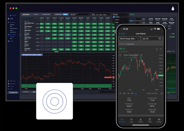
PipePatrol is very easy to use and it is installed on a dedicated server and operates completely autonomously.
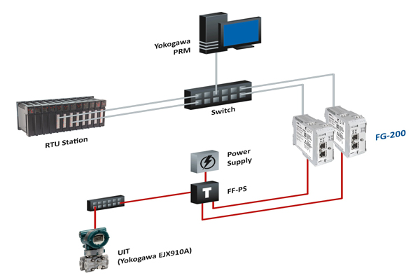
The user interface can runs on a separate workstation, or be integrated into an existing control system (Figure 2).
The user interface features intuitive operation: Only the information that the current user needs for his scope of work is displayed.
USE CASE STUDY
An example application in Canada demonstrates how quickly and precisely leak detection functions in practice.
A major oil and gas company operates several pipelines for which CSA Z662 Annex E applies.
Following thorough consultation, the company opted for the PipePatrol leak detection system.
During the project execution according to ISO 9001 standards, the documentation to fulfil CSA Z662 Annex E requirements was created and handed to the customer.
PipePatrol used the measurement values provided by the process control system and was integrated into the pipeline monitoring system at the customer’s request.
The leak tests performed for the site acceptance tests were conducted using valves in the pipeline to simulate leaks by real fluid withdrawal into a vacuum truck. The following results were achieved:
The first pipeline is a 24.69-km condensate pipeline. The location of the fluid withdrawal was close to the outlet flowmeter of the pipeline.
The detection threshold for leaks is set to 1.1 cu m/h.
After starting the leak test with a leak rate of 5 cu m/h, the system recognised the signature of the leak within 55 sec and went to "Leak Signature Detected" state.
After 2:30 min, it reached the desired statistical confidence level and raised the leak alarm.
At this point, only 208 l were spilled. Gradient intersection method calculated a leak position of 24.689 km, while Wave propagation method calculated a leak position of 24.677 km, both less than 0.1 per cent of pipeline length away from the real leak position.
The second pipeline is a 59.7-km sales oil pipeline. The location of the fluid withdrawal was close to the inlet flow meter of the pipeline.
The detection threshold for leaks is set to 3 cu m/h. After starting the leak test with a leak rate of 3.5 cu m/h, the system recognised the signature of the leak within 50 sec and went to "Leak Signature Detected" state.
After 6:40 min, it reached the desired statistical confidence level and raised the leak alarm.
At this point, only 380 l were spilled. Gradient intersection method calculated a leak position of 0 m, less than 0.1 per cent of pipeline length away from the actual leak position.
CONCLUSION
Modern leak detection systems are based on various mathematical and physical models.
The pipeline properties as well as regulatory requirements must be taken into account when selecting a system. The most advanced technology currently available is the E-RTTM model.
E-RTTM-based leak detection systems guarantee reliable leak monitoring for various types and lengths of pipelines, even under transient operating conditions.