
















































The solids control system is a core component of oil and gas drilling, and the shale shaker, acting as the primary key solids control equipment, directly dictates the drilling fluid recovery rate, drilling costs, and on-site environmental risks based on its separation efficiency.
Traditional operational modes rely on personnel to manually adjust parameters, such as the shale shaker’s deck angle, negative pressure, and inlet flow rate based on experience.
This results in issues including lagging response times, poor operational consistency, and a high likelihood of misoperation.
Data indicates that manual control can maintain the recovery rate of water-based drilling fluids at 85-95 per cent, and oil-based drilling fluids at 90-98 per cent.
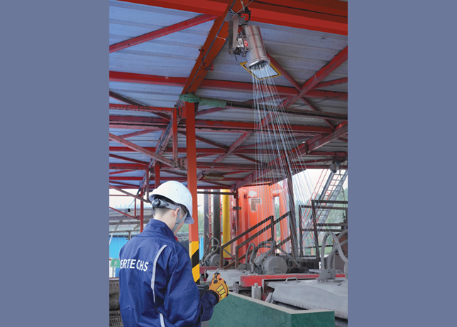
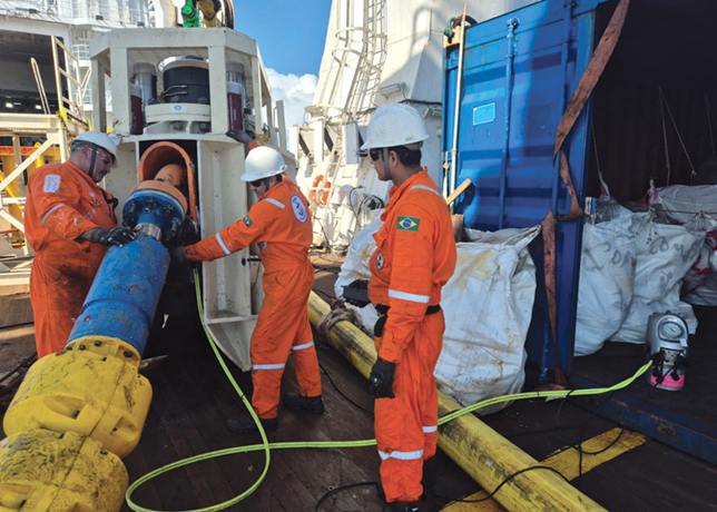
On-site deployment of the intelligent solids control equipment system
However, improper operation or delayed adjustments can cause the recovery rate to drop by an additional 8-10 per cent, leading to significant drilling fluid waste and the risk of overflow pollution.
Taking a 3,000-4000 m well with an 8½–12¼ inch wellbore diameter as an example, the drilling fluid consumption per well is approximately 1,200-1,500 cu m.
Under the traditional extensive management mode, the waste volume reaches 120-180 cu m.
For water-based drilling fluid alone, this can result in an invisible economic loss of approximately $70,588.
To resolve these issues, this paper details the development of an intelligent solids control equipment system based on visual recognition.
From the real-time recognition of the solid-liquid interface to intelligent parameter decision-making and closed-loop equipment control, it achieves full-process automation, substantially improving solids control efficiency and operational stability.
SYSTEM COMPOSITION & WORKING PRINCIPLE
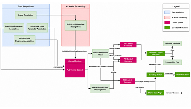
The system consists of three main components: An image acquisition unit, an AI control system, and on-site execution equipment (Figure 1).
It does not require any physical modification to the original main body of the shale shaker and features rapid deployment with plug-and-play capabilities.
• Overall workflow: The overall workflow begins with the image acquisition unit capturing real-time images of the shale shaker screen.
These images are processed by the AI model to recognise and calculate the precise position of the solid–liquid interface.
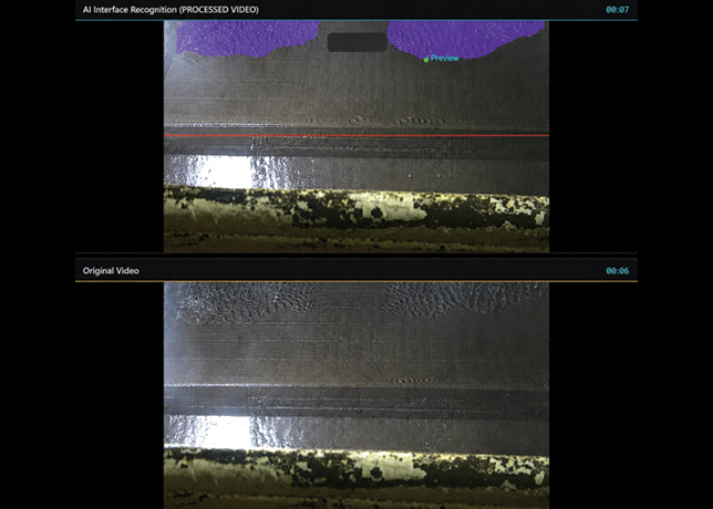
Figure 2 ... monitoring interface of the solid-liquid interface recognition system
The control system then automatically adjusts the parameters of the shale shaker and valves to maintain operation within the preset optimal range, while, under abnormal working conditions, it rapidly activates diversion mechanisms to completely prevent drilling fluid loss and overflow.
• Image acquisition unit: The image acquisition unit comprises a high-speed camera, heating device, defogging device, automatic supplemental lighting device, and an explosion-proof mounting bracket, enabling adaptation to drilling environments characterised by low temperatures, high humidity, heavy fog, and insufficient lighting.
Fog interference is mitigated through an oblique forward, downward-looking installation that avoids the upward path of vapour and works in conjunction with an explosion-proof exhaust fan for flow guidance to eliminate fog.
Condensation is controlled through built-in explosion-proof heating combined with automatic defogging and wiping functions to maintain lens clarity.
Night imaging is supported by a light sensor and adjustable supplemental lighting that automatically provide fill light in low-light conditions to ensure stable image quality.
• AI visual recognition model: The AI visual recognition model adopts a localised, lightweight architecture that operates without reliance on cloud computing support.
It offers low latency, high security, low cost, and offline functionality, allowing rapid positioning of the solid–liquid interface and timely trend judgement.
• Closed-loop intelligent control logic: The closed-loop intelligent control logic governs the shale shaker body, inlet valves, and bottom tank valves, with a particular emphasis on compatibility with negative-pressure shale shakers.
Under normal operating conditions, it automatically adjusts shaker speed, deck angle, negative pressure, and inlet flow rate to maintain the solid–liquid interface within the optimal solids removal zone, which lies across the outer one-third to two-thirds of the screen cloth.
When abnormal conditions occur, including sudden increases in buffer tank fluid level, the effects of trip gas or lag gas, or the onset of well kicks or overflows, the system responds according to the rapid forward-moving trend of the solid–liquid interface.
It opens the bottom valve and activates the backup shale shaker to divert fluid, thereby preventing drilling fluid overflow and associated environmental pollution.
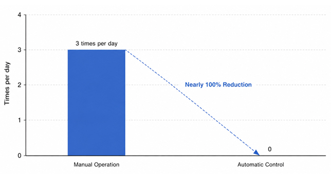
Figure 3 ... screen bypass times of the shale shaker under different control modes
FIELD APPLICATION CASES
This system has successfully completed industrial applications in multiple wells within the Sichuan region of China, demonstrating stable operation and remarkable results.
• Well Pu X (exploration and development well): For Well Pu X in Northeastern Sichuan Province, the system was applied to a KCl-polymer lubricating, sealing, and anti-sloughing drilling fluid with a density of 2.06-2.14 g per cu m and a viscosity of 42-75 seconds, at a drilling fluid cost of approximately $260-285 per cu m.
It operated continuously and stably for nearly four months, achieving fully unattended operation throughout the process, with no incidents of drilling fluid loss or screen blinding or overflow, while solids control efficiency remained above 90 per cent.
• Well Longye X (development well): For Well Longye X in Northeastern Sichuan Province, deployed in March 2026 and accumulating more than one month of operation, a typical working condition occurred during the static period at the bottom of the hole after tripping in, followed by circulation to remove trip gas (Figure 2).
As gas logging readings increased, the outlet drilling fluid flow rose rapidly and the solid–liquid interface moved sharply forward.
After AI recognition, the system responded within seconds by opening the bottom valve to divert the flow.
This prevented buffer tank overflow, avoided environmental pollution and drilling fluid waste, and ensured operational safety under complex conditions.
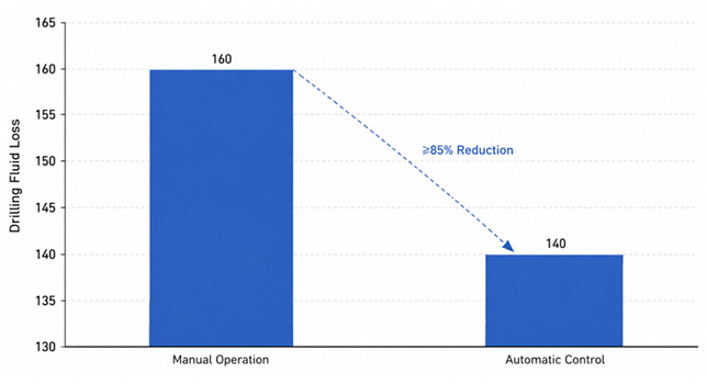
Figure 4 ... drilling fluid loss comparison under different control modes
APPLICATION EFFECTS & BENEFIT ANALYSIS
• Core Application effects: The system enables unattended operation by reducing manual intervention by 95 per cent and thereby lowering on-site operational intensity.
Across all working conditions, drilling fluid loss, screen overflow, and environmental pollution remain at zero, while efficiency at the optimal solids removal position on the shale shaker is consistently maintained at or above 90 per cent (Figure 3).
The system adapts reliably to complex scenarios involving low temperatures, high humidity, nighttime operation, and trip gas effects, providing timely closed-loop responses.
• Economic Benefits: Using a conventional 3,000-4,000-m well as a baseline, drilling fluid waste is reduced by 120-180 cu m per well, representing a reduction of more than 90 per cent when this system is deployed.
Direct cost savings for water-based drilling fluid amount to approximately $70,588 per well, and the reduction in wear on solids control equipment together with the decrease in non-productive time contributes to significant overall economic benefits (Figure 4).
• Safety and environmental benefits: The system eliminates environmental damage arising from drilling fluid loss or overflow and reduces the need for manual, close-range operation of equipment, thereby lowering associated safety risks.
It also supports broader industry trends toward intelligent and environmentally responsible drilling practices.
SYSTEM PERFORMANCE SUMMARY
The intelligent solids control system based on visual recognition can accurately and in real time identify the shale shaker’s solid–liquid interface, enabling full-parameter closed-loop intelligent control.
Field application demonstrates that solids removal efficiency remains stable at or above 90 per cent, drilling fluid loss is reduced to zero, and manual intervention is decreased by 95 per cent, resulting in genuinely unattended operation.
The system provides advantages including rapid deployment, strong adaptability, offline capability, and high safety and reliability, contributing to reduced drilling costs alongside improved environmental protection and safety levels.
Its low hardware cost and straightforward modification requirements for existing equipment further support rapid on-site adoption and continued optimisation.