


 Samref ... adopted SAP R/3 system
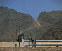
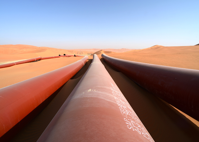
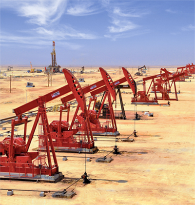
Saudi Aramco's extensive buried pipelines are protected by a combination of coatings and cathodic protection.
The operating temperatures range from 65¡C to 120¡C.
Before 1980, the coating systems included tape wrap, coal tar epoxy, and polyethylene.
Fusion bonded epoxy (FBE) coatings, however, have dominated the post 1980s coating systems.
FBE coatings are primarily applied in a coating plant and are impractical for large scale coating renovation in the field. Coating renovation is commonly used to ensure effective corrosion control of the external surfaces of pipelines with badly deteriorated coating.
However, it is very expensive given the expenditure for excavation of the lines, removal of the old coating, and application of the new epoxy-based liquid coating systems.
Khuff gas flow-lines are of particular concern to Saudi Aramco since these lines have experienced serious temperature-induced coating failures.
The high temperatures in these pipelines, exceeding 105¡C, have in many locations destroyed the FBE coatings on the pipelines after approximately five years in service.
Considering that conventional corrosion protection (CP) is often ineffective on buried pipelines with severely degraded external coatings, large sections of the Khuff gas lines require complete coating renovation at approximately five year intervals to maintain adequate external protection.
A number of major oil companies worldwide have utilised distributed polymeric anode cables as an alternative to pipeline coating rehabilitation because of its cost-effectiveness compared to re-coating.
For example, Chevron Pipeline Company has used continuous polymeric anodes since 1986 as an alternative to pipeline rehabilitation with resounding success.
In addition, Transcontinental Gas Pipeline Corporation has installed more than 240 kilometers of continuous polymeric anodes since 1984 for its 30" to 48" trunk lines. No failures have occurred to date, essentially because of the following unique advantages of polymeric anodes when compared with conventional remote cathodic protection systems:
Chevron spent about 30 per cent of the estimated coating renovation cost for 8" pipelines to install the CP systems using polymeric anodes.
For 30" to 48" pipelines, Transcontinental Gas Pipeline Corp. also spent about 30 per cent of the estimated coating rehabilitation cost to install polymeric anode CP systems. In both cases, there was no interruption of service, resulting in additional savings.
Although the application of polymeric anode technology is worldwide and gaining ground, its use in the Middle East is only just beginning with recent introductions by Petroleum Development Oman (PDO) and the Yanbu facilities of the Saudi Aramco Mobil Refinery Company (Samref).
Saudi Aramco conducted both laboratory testing and field evaluations to determine if continuous polymeric anodes can replace pipeline-coating renovation. The objective of the laboratory test programme was to assess the effect of current density and environmental factors such as temperature and type of sand on the integrity of commercially available conducting thermoplastic anode cables.
The purpose of the field evaluation was to assess the effectiveness of continuous polymeric anodes in providing cathodic protection to pipelines with severely degraded coatings.
This also included the evaluation of the design and installation of polymeric anode systems.
Evaluation
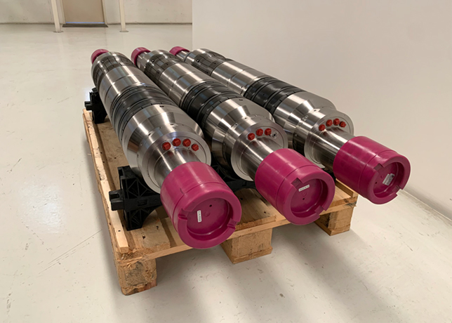
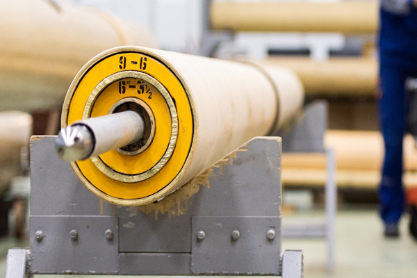
The laboratory testing samples were prepared from commercially available polymeric anode cable.
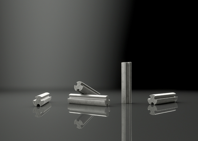
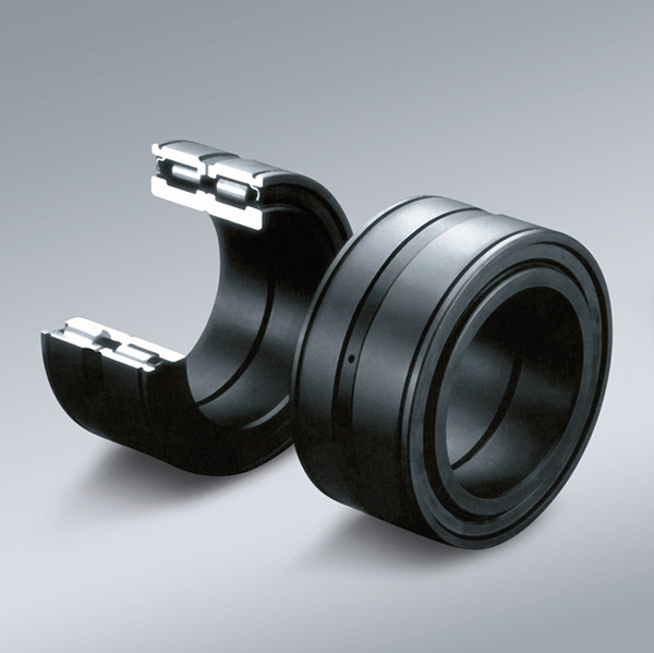
This anode consists of a stranded #6-AWG copper conductor covered with a conducting polymeric composite of cross-linked linear low-density polyethylene (LLDPE), plus a proprietary highly conducting carbon black.
For ease of transportation and installation, the anode cable is encased inside a porous woven LLDPE jacket packed with a high performance coke breeze for a total anode diameter of approximately 3.8 cm.
The amount of coke breeze compacted around the anode, approximately 2.2 kg per linear metre, is designed to allow the polymeric anode cable to last 20 years at the maximum recommended anode current output of 52-mA per metre (16-mA/ft).
The laboratory test programme utilised twelve, nominal four-foot long, 0.92-metre actual test length, uncoated g-blasted, carbon steel pipes.
Polymeric distributed anode cables were embedded in soil (damp subkha soil and coarse sand) inside the pipe sections and wired for the cathodic protection of the internal surfaces of the pipes.
The surface area of the bare steel test vessels was significantly larger than was required for the maximum applied current density. This ensured that the anodes were tested at their endurance limit.
The polymeric anodes were operated at applied current levels of 8-mA and 16-mA per linear foot of anode, which resulted in current densities of 20.7-mA/m2 and 41.4-mA/m2 on the bare cathode surfaces.
The test duration was 375 days at ambient, 40¡C, and 60¡C.
To maintain the sand (both subkha and coarse sand) moist at all times, a five per cent brine solution was added periodically.
Allowance was made for venting possible gaseous products resulting from the electrochemical reactions taking place within the coke breeze contained around the anode.
At the end of the 12-month test-period, the internal surfaces of all the pipes were examined for evidence of corrosion.
The external surface of the LLDPE jacket was rinsed with distilled water, air dried and then rephotographed. The physical, heat-distortion, and cold bend properties of the cross-linked conducting polymer of the anodes were then measured.
Results
Visual observations made after the exposure test showed that the polymeric anode cables suffered no significant deterioration when tested for 12-months at the endurance limit recommended by the anode manufacturer; namely, a maximum anode current level of 16-mA/linear foot and a temperature of 60¡C.
There was no significant consumption of any of the polymeric anode cables. The anodes were in excellent condition and looked new.
Some of the polymeric anodes exposed to an anode current level of 16-mA/ft and 60¡C, exhibited what appeared to be blisters on the porous LLDPE jackets.
It is suspected that gas generated on the external surface of the coke breeze layer caused the blistering. The blisters disappeared about three days after termination of the experiments.
All the anodes tested, except one, remained intact; the coke breeze was still kept in place by the porous woven LLDPE jacket. For one sample, the polymeric anode cable remained unchanged and encased in the coke breeze without the LLDPE jacket. The amount of coke breeze lost in each sample during the test period was insignificant.
At the maximum anode current level of 16-mA/ft, the expected coke breeze consumption rate is 1 kg/amp-year. Consequently, the service life of the coke breeze could indeed last for more than 20 years.
There was clear evidence of ongoing corrosion activity during the test. The internal surfaces of the test pipes that contained coarse sand exhibited the worst corrosion activity.
Elevated temperature, constant addition of salt-water and inadequate anode current density all contributed to the observed corrosion.
The applied anode current levels of 8-mA/linear foot and 16-mA/linear foot, or cathode current densities of 20.7- and 41.4-mA/ m2, were intended to ensure that the anodes were tested at their endurance limit. To achieve complete cathodic protection would have required 80 to 110-mA/m2 for bare steel (cathode current density).
The system achieved steady state within the first month of operation except for one pipe section.
For subkha soil, the current remained essentially constant. Likewise, the resulting potential for subkha soil remained essentially constant.
Three of the pipes had accidental disconnect problems during a portion of the monitoring period resulting in anode potentials of 1.4 to 13.5 volts.
The potential versus time plots at 40¡C and 60¡C show spikes indicative of the weekly addition of salt-water to the sand to facilitate current density control.
The anode potential increased with increasing dryness of the sand but dropped to a low value whenever additional salt-water was added to the sand. This is reflected in the spikes in the anode potential versus time plots.
After the 12-month test period, physical, mechanical and chemical properties of all the samples were measured to determine any changes. The test results indicate an insignificant change in the properties of the conducting polymer in such conditions.
Field study
The field evaluation of the polymeric anodes also utilised commercially available prepackaged polymeric anode.
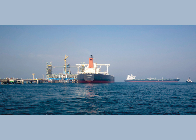
Approximately 6,700 metres of the polymeric anode were installed continuously along a 6.7 km gas loop-line that has a diameter of eight inches and extends from the wellhead to the pipe manifold.
This loop-line also runs in parallel with a flowline between the wellhead and the pipe manifold area.
These pipelines have FBE coatings on their external surfaces, and have been receiving cathodic protection primarily from two 50-A remote deep anode beds.
These anode beds are located in the wellhead and manifold areas, or at the ends of the pipeline. During the first 10 years of service, the FBE coatings were severely damaged by the high temperature of the carried gas.
It was decided to use cathodic protection through continuous polymeric anode to protect the line without coating renovation.
During the evaluation of the polymeric anode systems, insulation flanges were installed to electrically isolate the loop-line from the well, the flowline, and surrounding metallic structures.
According to the polymeric anode manufacturer, the 6,700 metres of anode can supply a maximum current output of 348 amperes, or 52-mA per linear metre.
However, due to the current requirement of this pipeline, the design restricted the current output of the anode below 96-A or 14.3-mA per metre.
At this anode current output, the pipe received a maximum current density of approximately 18.8-mA/m2, which is less than the Saudi Aramco current density criterion of 20-mA/m2 for bare steel.
Actual field data indicates that this design current density is more than adequate to protect the external surface of the pipe, since the pipe's external surface was not completely bare.
According to the anode manufacturer, at the maximum allowable current level of 52-mA per linear metre, the anode would last 20 years.
Based on the reduced current density in the field-testing, the installed anode is expected to last significantly more than 20 years.
For optimising the anode current distribution along the pipeline, this 6,700 metre anode was divided into four equal-length segments of 1,675 metres each.
Four 24-V, 24-A rectifiers: two oil-cooled and two air cooled types, control these four anode segments.
For each rectifier (CP system), the design required dividing the 1,675 metre anode segment into four legs with an average length of approximately 419 metres to optimise the anode current distribution.
Two anode legs were attached to a junction box, and each one has a resistor that is used to balance the current output.
All connections between, anode legs to junction boxes, junction boxes to junction boxes, junction boxes to rectifiers, and the connections between the protected pipeline and the rectifiers, utilise AWG No. 2 HMWPE cables.
The soil resistivity along the pipeline varied from a few thousand ohm-cm to more than 10,000 ohm-cm.
The design of these CP systems employed an average value of 5,000 ohm-cm.
System design
In this field evaluation, the anode legs were installed between the loop-line and flowline.
The distance between the loop-line and flowline is in the range of six to 10 metres.
The design requires proper locations for the anode legs to minimise the effects of heat from the pipeline and to optimise anode current distribution.
Based on results of a test for temperature gradient around a heat source in sand, keeping the anode legs within a range of three to five metres from the loop-line would minimise heat effects and optimise anode current distribution.
The anode legs were placed at the bottom of a trench with a depth of one metre. The anode manufacturer required heat shrink encapsulations to protect all the connections between the header cables and anode strings.
After laying the anode, the entire trench was backfilled with clean sand.
Monitoring
Monitoring the CP levels on the loop-line required 16 permanent copper/copper sulphate reference electrodes installed at eight different locations, along the pipeline.
The permanent reference electrodes were located approximately six-inches from the pipe and at the three and nine-o'clock positions around the pipe.
The backfill surrounding the reference electrodes consists of a mixture of clean sand, gypsum, and bentonite to retain moisture around the electrodes. In addition, two coupon test stations were installed to enhance the CP level monitoring.
This article, by B Q Pham, O Olabisi, S A Al Zubail, J K Boah, A L Lewis, A H Al Rasheed and A A Al Jabran of Saudi Aramco, was presented to the 9th Middle East Corrosion Conference and Exhibition in Bahrain and appears here courtesy of the Bahrain Society of Engineers and NACE International.