

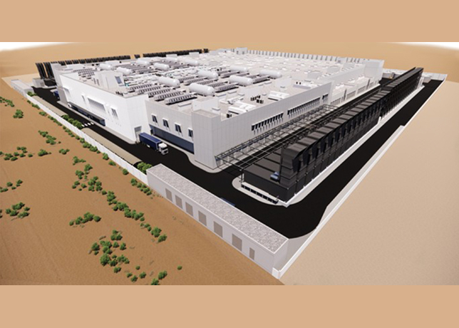


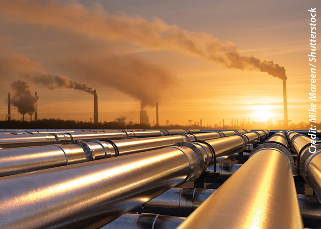


As part of the Kingdom’s objective to protect the environment, Saudi Aramco showed its commitment to maintaining the highest standards in air quality control by approving funds to introduce Superclaus technology into sulphur recovery units (SRUs) at the Berri Gas Plant (BGP).
In addition to installing two new Superclaus units, three other SRUs will be upgraded to the same new technology. As a result, all SRUs will be able to achieve 99 per cent recovery efficiency instead of the typical Claus process efficiency of 95 per cent. Consequently, the enhanced sulphur recovery efficiency (SRE) will keep the 502 ground-level concentration within the level set by the Saudi Arabian Presidency of Meteorology and Environment (PME) environmental regulations, despite significant sulphur production at BGP. This article introduces the Superclaus process as a new proven technology and discusses its implementation in BGP SRUs as part of the Qatif and Abu-Safah Development Program.
Sulphur hike
By July 2004, associated gases from Qatif and Abu-Safah fields will be processed in the BGP. As a result, the sulphur production will increase to more than double its current level at BGP Consequently, the recovery efficiency will have to be increased to control sulphur dioxide emissions at the level set by the PME environmental regulations that limit the SOZ ground level concentration (GLC) to 730 ug/M3 (0.28 ppm).
To meet PME requirements in the Jubail area with regard to SOZ GLC, the dispersion modeling conducted revealed that SRE should increase from its typical level of 95 per cent to 99 per cent.
The current Claus process cannot achieve this new recovery requirement. Therefore, different technologies that can meet such high recovery efficiency, such as sub-dewpoint and amine tail gas treatment processes, have been explored. Eventually, the Superclaus process was selected due to its simplicity compared to other evaluated processes.
Actually, the Superclaus process is fully integrated within the existing Claus process and does not require a separate tail gas treatment unit. Fig. 1 shows the Superclaus section bordered by the dashed red line frame. Three-D models for new Superclaus units are shown in fig. 2.
New technology
In 1988, Jacobs Netherlands (COMPRIMO) patented an improved Claus process called the Superclaus process. The main difference between Claus and Superclaus is the application of direct oxidation of H2S to sulphur with a high yield in the third converter (CV3) over the special catalyst instead of the thermodynamically limited Claus equilibrium reaction of SO2 with H2S. This milestone in the development of the Claus process brought the overall sulphur recovery efficiency to 99 per cent utilising the same equipment.
Breakthrough theory
The Superclaus process is based on a special catalyst that uses iron on silica for selective oxidation of H2S to elemental sulphur in the last reactor (CV3) as shown in the following reaction:
Superclaus reaction (1)
H2S + 1/2O2—>S + H20
This reaction is thermodynamically complete, and therefore, high conversion levels to elemental sulphur can be obtained. The key feature is the design of the catalyst, which prevents the reverse Claus reaction:
Claus reaction (2)
2H2S + SO2 <-> 3S + 2H20
Reverse claus reaction (3)
3S + 2H20 <-> 2H2S + SO2
More important, the catalyst does not catalyse the oxidation of the formed sulphur vapor to the thermodynamically stable SO2:
Sulphur oxidation reaction (4)
S + O2 <-> SO2
In the Superclaus process, the conventional H2S: SO2 is 2:1 ratio is no longer applied. Instead, the H2S concentration in the gas leaving the second claus stage is controlled between 0.7 - 1.0 vol.per cent.
The Claus reaction (2) takes place in the thermal reactor as well as in both Claus converters, but with excess H2S. The equilibrium shifts in such a way that the S02 concentration in the gas will be suppressed. The excess H2S compared to S02 results in a more reduced process gas, which is favorable for a reduced sulfate content on the Claus catalyst and results in better catalyst activity.
Typically, the gas leaving the second Claus stage may contain concentrations of 0.8 vol.per cent H2S and 0.08 vol.per cent S02. Also, the Superclaus reactor is operated with 2.0 vol.per cent excess air.
Component break-down
As shown in the process flow scheme, fig. 1, a new sulphur recovery unit with the Superclaus process consists of the following parts:
Feed gas system
The acid gas from the upstream Gas Treating Amine Units (DGA Units) at 12 psig and marginally above the ambient temperature enters the SRUs and passes through the Acid Gas Scrubber, in which it is contacted with a circulating flow of chilled water. In this way traces of solvent (DGA) are removed from the gas, and the gas is cooled so that a part of the water vapor present in the feed gas is condensed. The acid gas from the scrubber enters the Acid Gas KO Drum, in which entrained water is separated from the gas. Then, the acid gas is preheated by means of high-pressure steam to 230 deg C (446 deg F) before it is routed to the reaction furnace burner.
Thermal stage
This stage is the core of any Claus/Superclaus SRU. More than 60 per cent of sulphur is formed in this stage in the straightthrough process configuration. The acid gas flows to the reaction furnace burner (RFB), where it is burned substoichiometrically with air. The combustion air to the RFB is supplied by the combustion air blowers and preheated to 37 deg C (700 deg F) before it enters the burner. The combustion air is divided into two streams. The major portion (-95 per cent) is charged to the RFB, and the remaining quantity is mixed with the tail gas coming from the second Claus stage.
The air to the burner is exactly sufficient to completely oxidise all hydrocarbons present in the acid gas and to burn as much H2S as is required to obtain 0.8 vol.per cent H2S at the outlet of the second catalytic stage.
The partial burning of H2S takes place in the RFB and its combustion chamber to produce S02, which is required for the subsequent Claus reaction (2) at 1,037 deg C (1,900 deg F):
H2S Burning reaction
3H2S + 1.502 -> 2H2S + S02 + H20
To remove the heat generated in the RFB and its combustion chamber, the gas passes through the tube bundle located in the reaction furnace (RF). The gas is cooled, and saturated high-pressure steam is thereby generated at 600 psig. After leaving the RF at 315 deg C (600 deg F), process gas is introduced into the first condenser (CD1), where it is cooled; the sulphur vapor is condensed; and liquid sulphur is separated from the gas at 173 deg C (345 deg F). As a result, low-pressure (60 psig) steam is generated in the shell side.
Catalytic stages
The catalyst beds in these stages are basically Ti02 supplemented by a top layer of conventional activated alumina catalyst. The gas stream from the first condenser passes through the first stage steam reheater (RH1) to obtain the optimum temperature for the catalytic conversion. The first converter (CV1) inlet temperature is maintained at 235 deg C (455 deg F). This is favorably high to obtain the almost complete COS and CS2 conversion in the bottom of the catalyst bed at 315 deg C (600 deg F):
Hydrolysis Reaction (6)
COS + H20 -> CO2 + H2S COS
Hydrolysis Reaction (7)
CS2 + 2H2O -> C02 + 2H2S CS2
H2S and S02 react over the catalyst until equilibrium is reached as in Claus reaction (2). The effluent gas from CV1 is cooled in the second condenser (CD2) to 171 deg C (340 deg F). Again, liquid sulphur is produc ed during gas cooling, and low-pressure steam is generated.
The process gas passes to the second stage steam reheater (RH2) where it is heated to 210 deg C (410 deg F). Again, the gas is subjected to conversion in the second converter (CV2) per a Claus reaction (2) and cooled in the third condenser (CD3). The outlet temperature of CV2 is 226 deg C (440 deg F), which is lower than in CV1 and promotes a high conversion rate of H2S and S02 into sulphur.
Superclaus stage
To obtain a high sulphur recovery, the process gas is passed to the third and final catalytic stage, the Superclaus stage. The oxidation air is injected into the process gas upstream in the third stage steam reheater (RH3), where mixed gas is heated to 210 deg C (410 deg F). H2S is selectively oxidised into sulphur in the third converter (CV3) over the selective oxidation catalyst (Fe-S’02 with a-A1203 inert) according to Superclaus reaction (1).
This reaction is thermodynamically complete, and therefore, high conversion levels to elemental sulphur can be obtained. The air is supplied in excess to maintain oxidising conditions in the converter and prevent sulfiding of the catalyst.
The gas leaving CV3 passes to the fourth condenser (CD4) at 260 deg C (500 deg F). To condense as much sulphur vapor as possible, CD4 operates at a low temperature, 126 deg C (260 deg F). This is obtained by generating very lowpressure steam at 13 psig, which is condensed in an air fin steam condenser and returned back to the fourth condenser. Downstream CD4, the process gas flows into the coalescer (CL), which is provided with a demister pad, in which the last traces of liquid sulphur are separated from the gas.
To avoid catalyst damage in upset cases, the Superclaus stage is equipped with a bypass line and switching valves to bypass the Superclaus reactor without taking the entire SRU out of operation. In such cases, the process gas from CD3 is routed via the Superclaus bypass directly to CD4.
Thermal Oxidiser
The Superclaus tail gas and the vent gas from the sulphur pit contain residual H2S that should not be released directly into the atmosphere. These gases are therefore thermally oxidized to convert residual H2S and sulphur vapor into S02 in the presence of air in the thermal oxidiser. The gases to be oxidised are heated by mixing them with hot fuel gas. The hot gas is obtained by combustion of fuel gas in the oxidiser burners. The fuel gas flow to the burner is adjusted by control of the temperature in the thermal oxidiser. Air is provided by a natural draft. The hot gases leaving the oxidizer are discharged via a stack to the atmosphere.
Sulpher pit and de-gassing process
The sulphur produced from condensers (CDs), which contains about 300 ppm H2S, overflows through sulphur seals and drains to the sulphur pit. The H2S is partly chemically bound as polysulfides and is partly physically dissolved. Degasification by means of the Shell degasification process reduces the H2S content to less than 10 ppm. Degasification is obtained by injecting air via bubble columns in the liquid sulphur. In this way, the dissolved H2S is partly stripped from the sulphur and partly oxidised to elemental sulphur. Furthermore, the removal of H2S from the sulphur promotes the decomposition of the polysulfides into H2S and sulphur.
Superclaus in BGP
In addition to two new Superclaus units, three other Claus units will be upgraded to Superclaus process with 99 per cent recovery efficiency. The modifications have been determined for the retrofit of existing units to accommodate the Superclaus process operation:
The main burner control and instrumentation will be upgraded to an advanced burner control (ABC) system to meet the accurate control requirements for the Superclaus operation mode. The required quantity of air is calculated by measuring the acid gas flow and multiplying this flow with its required ratio air to acid gas (feed forward). The resulting air demand sets the flow control system in the air supply to the burner. The flow control system is adjusted by the H2S analyzer controller (feed back control) located in the process line upstream of the Superclaus stage. It ensures an H2S content of 0.8 vol.per cent in the process gas to obtain the optimum sulphur recovery efficiency of the unit.
The existing main burners will be replaced by high-intensity burners to enhance the oxidation reactions by efficiently mixing the air with acid gas. This is done by bringing the air into rotation. This results in a short flame and avoids oxygen slip to the catalytic stages, which would result in the catalyst deactivation. The new burners will be equipped with an electronic ignition system and advanced burner management system (BMS).
Existing reaction furnace combustion chambers will be replaced by larger ones to ensure sufficient residence time for the destruction of aromatic hydrocarbons present in the feed, which are mainly benzene, toluene and xylene (BTX). The new combustion chambers will include throats to maximize the mixing of the process gas. Also, they will include radiation walls that keep the heat in the chamber for the complete destruction of BTX and that protect the reaction furnace tube sheet against radiation.
The Claus catalyst charges will be replaced by a fresh catalyst based on Ti02 to ensure sufficient hydrolysis of COS and CS2. This catalyst will be supplemented by a top layer of conventional activated alumina catalyst. The new Ti02 catalyst is resistant to sulfation.
The second and third stage inline burners will be replaced by steam reheaters. The main advantage of using steam exchangers instead of inline burners is minimisation of the amount of feed bypass around the main burner, which will result in permanent loss of the recovery as SO2. Also, the oxygen slippage to the reactors that would result in catalyst deactivation will be minimized.
The third converter stage will be reused as a Superclaus reactor, and for this reason, the Claus catalyst will be replaced by a Superclaus (Fe-Si02 with a-A1203 inert) catalyst.
An oxidation air line with a control loop will be installed to provide the required amount of air to selectively oxidize the H2S into sulphur in the Superclaus reactor.
A bypass line with switching valves will be installed around the Superclaus stage to avoid catalyst damage in upset cases.
The fourth sulphur condenser and its associated closed-loop steam condenser will be replaced by a new one with larger heat exchanging surface areas to absorb the increased heat input resulting from Superclaus operation.
To ensure proper Superclaus operation and control, the old analyzers will be replaced by the latest developed AMETEK tail gas analyzers. The new analyzers will be located downstream from the third condenser. Such advanced monitoring devices will maximize the SRE.
To achieve the maximum possible SRE, a coalescer will be installed downstream from the final sulphur condenser to prevent sulphur entrainment to the incinerator, as this is a permanent loss in recovery.
Conclusion
All SRUs in BGP will be able to achieve 99 per cent SRE by applying the Superclaus process, which uses the following two innovative concepts:
• A catalyst for selective oxidation of H2S to sulphur, rather than to SO2, and a less sensitive and more flexible air-to-acid gas control; and
• Despite the significant increment of sulphur production at BGP, the enhanced SRE will control sulphur dioxide emissions below the limit (730 ug/M3 GLC) set by PME environmental regulations to protect the environment.