


Most engineering work processes are not sequential, but instead are parallel and interactive. Many aspects of the design and work process require specific review and alignment with other engineering disciplines or customers prior to implementation. It is when all pieces come together and need to be ensemble and integrated that data visualisation and design validation acquire a key role.
The development of 3D design has opened a broad range of possibilities, allowing engineers to explore more design options and processes. The larger the project or the more complex, the larger the chance of encountering clashes in the design of the different engineering and structural components. Therefore the need to develop tools that enable design validation and ensure clash-free projects from design to construction and maintenance phases.
Clash detection allows for the effective identification, inspection and reporting of interferences in a 3D project model and ensures model consistency through analysis and integration of its components. The ability to explore options and maximise design can and should be done via the virtual construction of models during the conceptual design phase, hence reducing the construction schedules, in the case of greenfield projects; and minimising the impact in the plant, in the case of brownfield projects.
The tools available nowadays enable to conduct clash tests between traditional 3D geometric figures and laser-scanned point clouds. Dynamic collision detection functions show objects that share the same 3D space. Collisions are reported as groups of objects are driven through the model with a mouse or a joystick, as well as with precision controls.
These interferences and clashes can be automated and enforced for specific projects, becoming customised rules. Once installed as a custom clash test, can be reused by anyone during different phases of the project. The entire batch of tests can be selected and run directly. Custom clash tests are an excellent way to roll out a standardized set of tests across an organisation.
Among different tools in the market, Intergraph SmartPlant 3D and SmartPlant Review offer a host of features to detect, mitigate and avoid clashes between various physical components of a plant at the time of 3D design. SmartPlant 3D offers two modes in which clash detection (or interference checking) may be performed. In the unique interactive mode, it offers immediate feedback to designers by notifying them of the clashes as modeling is being performed. In this manner, it serves as a clash avoidance mechanism as it prevents the clash from ever occurring thus eliminating the need to detect it at a later point of time and address it.
In addition to the interactive mode, a robust clash checking service that is deployed on a server constantly checks for clashes in the background. This service efficiently detects clashes for all newly created and modified objects and logs them to the SP3D database. Tools are provided to review such clashes, report on them, approve them and take any other action to mitigate them.
The clash checking capabilities of SmartPlant 3D can be leveraged for both greenfield and brownfield projects. In the case of greenfield projects, clash checking can be extended to data supplied by joint venture partners in addition to native SmartPlant 3D data. Data provided by vendors or joint venture partners may be from various tools such as another SmartPlant 3D model, PDS, PDMS, CADWorx, Tekla, Speedikon, InRoads and so on.
In addition, intelligent and non-intelligent 3D graphic data in the form of XMpLant, Microstation .DGN files, Autocad .DWG files and .SAT files can also be clashed against. All such external data can be referenced into the SmartPlant 3D model using the Reference 3D (R3D) technology so that clash checking and several other value added functions such as visualising and reviewing, measuring and modeling against, reporting, drawing generation etc, may be performed against such data.
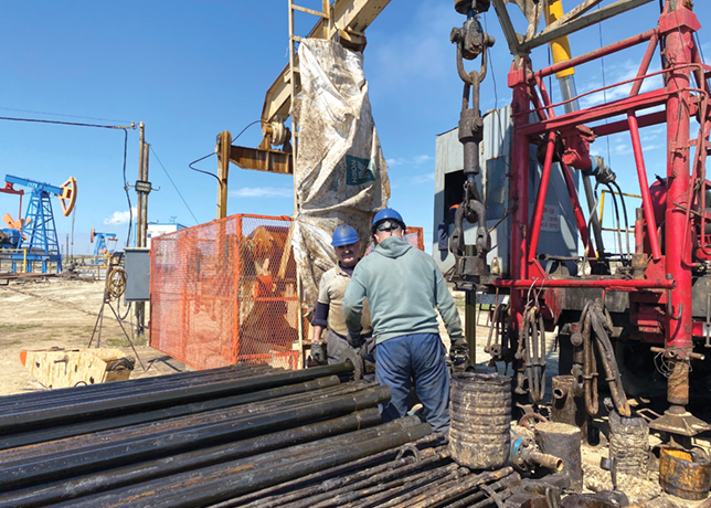
To aid brownfield project workflows, SmartPlant 3D has the capability to reference in laser scanning point cloud data from several vendors (Leica, QuantaPoint, Trimble, Z&F). If 3D Cad models of the brownfield project exist (either the original Cad model or converted models), they can be referenced in using the Reference 3D technology as well. SmartPlant 3D detects clashes against the point cloud data in the same consistent manner as it detects clashes against other SmartPlant 3D and Reference 3D objects. This allows for clash free designs that reduce construction costs and delays.
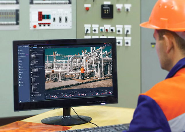
3D solutions can be empowered with SmartPlant Review, the complete visualisation environment for interactively reviewing and analysing large, complex 3D models of process and power plants. The software provides all the visualisation tools needed to review designs during engineering, construction, or maintenance. SmartPlant Review provides views from any perspective so layouts can be reviewed more effectively than with traditional engineering models. Integration with laser scanning data
3D designer and engineers can enjoy nowadays a virtual site presence within their native review environment. Project and design teams can review, visualise, and dynamically interact with real world 'as-found' point cloud conditions and a fully-rendered PDS or SmartPlant 3D design model. The result is greater confidence in assessing a design’s impact on construction and/or operations.


