
By Jimmy D Kumana and Ali H Al-Qahtani
Abstract
Optimisation of manufacturing processes is a two-step activity. In the first step, one must create the right process structure or topology.
In the second, one must follow up by mathematically optimising the numerical values of the important process parameters.
Conventional mathematics is not suitable for qualitative decisions such as those required for optimising the topology of a chemical process. Attempts to conduct a parametric optimisation based on "superstructures" have been successful only for small academic problems, not for large real problems. Over the past 25 years, much better success has been obtained using recently developed heuristic optimisation techniques collectively known variously as "process integration," "pinch analysis" and "pinch technology."
The basic concepts and design rules of pinch analysis are reviewed, and applications to important industrial problems are out lined, including: heat exchanger networks; combined heat and power systems; emissions optimisation of combustion gases; cryogenic processes; chemical reaction systems, including catalysis; distillation column sequencing; distillation column design for energy efficiency; batch crystallisation; production capacity debottlenecking; water conservation; distributed wastewater treatment facilities; refinery hydrogen management; and manufacturing supply chain management.
Some of the applications are mature. Others are still in the R&D stage. Pinch analysis is presented as a general-purpose optimisation tool, with applications limited only by the user's imagination and ingenuity (1). The emphasis is on finding the optimum process configuration (topology) using simple heuristic rules rather than numerically optimising parametric values.
Introduction
In the early 1980s, against a background of the so-called "energy crisis," pinch technology emerged as a tool for the design of heat exchange networks (HENs). Its key feature was to give the engineer simple concepts to use interactively, enabling him to stay in control. Applying pinch analysis (as it is now called), the engineer could calculate the "target" energy requirement for any process and produce thermally efficient and industrially acceptable designs that took account of operability, plant layout, safety, startup, etc.
The basic concept is simple: The performance of any system is always limited by a single constraint - the pinch just as the strength of a chain is determined by its weakest link. If one needs a stronger chain, pinch analysis teaches that the most cost-effective strategy is not to replace the chain with a new one, but to increase the strength of the existing chain by selectively replacing the weakest link(s).
Pinch analysis achieved almost instant acceptance as a superior approach to the design of optimum HENS, with proper account being taken of capital costs and payback requirements. Typical fuel savings were 20 percent or more, compared to the existing or previous best design. In the next major advance, pinch analysis was extended to the analysis of on-site utilities, such as boilers, turbines, heat pumps and refrigeration systems, and techniques were developed for optim1um design of combined heat and power (CHP) systems.
During the last decade, pinch analysis has evolved from this specialised tool for energy efficiency improvement into a broad-based methodology for reducing capital costs, minimizing environmental pollution (NOx, SOx, VOC and wastewater), freshwater conservation, wastewater treatment system design, batch process scheduling, capacity debottlenecking in both processes and utilities, and site development planning. The most recent applications have been in the management of chemical species such as HZ and S in oil refineries and the optimum combination of reactors and separators. (2, 3, 4, 5, 6, 7, 8, & 9).
Pinch approach
The general pinch approach is shown in fig. 1. The complex multi-dimensional problem is first transposed into the pinch format, which plots simplified "composite curves" of resource (energy, water, etc.) demand and availability. Then targets are set, and a broad set of pinch design rules are used to create a design that approaches the targets as closely as economically and practically possible. Working in this transposed environment gives the engineer a simple visualisation of even the most complex problems and enables quick assessment of alternatives, including outline economics. Constraints can easily be considered and either overcome or accepted. Finally, the pinch environment is transposed back to process flow diagram (PFD) form, and the conventional steps of simulation, feasibility checking and detailed design are completed.
This paper provides a general overview of nine major applications of pinch analysis:
• Thermal Energy Efficiency and Design of HENs.
• Power Conservation and Recovery.
• Total Site Energy Analysis.
• Water Pinch and Distributed Effluent Treatment.
• Integrated Process Debottlenecking.
• Batch Process Optimisation.
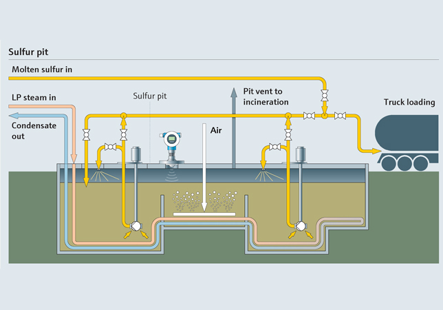
• Oil Refinery Hydrogen and Sulfur Optimisation.
• Complex Distillation Systems.
• Combined Reaction/Separation Systems.
Thermal Energy Efficiency and Design of HENS
All chemical manufacturing processes require energy in the form of heat and power. Power is consumed both for shaft work (to drive industrial machinery) and for process cooling. The individual process heating duties can be combined into a single "cold composite curve" drawn on a temperature enthalpy (T H) diagram; it represents the enthalpy demand profile of the process. Similarly, all the cooling duties can be combined into a single "hot composite curve," which represents the enthalpy availability profile of the process.
When both curves are plotted on the same T -H diagram, as in fig. 2, they show the opportunity for heat recovery as well as the minimum net heating and cooling requirements.
The point of closest approach, where available temperature driving forces between hot and cold streams are at a mini mum, is called the process pinch. It separates the overall process into two distinct thermal domains:
• A net heat sink above the cold pinch temperature, meaning that hot utility must be supplied.
• A net heat source below the hot pinch temperature, meaning that cooling must be provided.
The temperature difference between hot and cold streams at the pinch is called the minimum approach temperature (MAT). For each value of MAT, there are corresponding values of minimum heating and cooling requirements (Qh)m;" and (Qc)I,,;n. These are the energy targets.
In order to achieve the targets, the HEN design must satisfy three conditions:
• No hot utilities are used below the pinch temperature.
• No cold utilities are used above the pinch temperature.
• No heat is transfered from hot streams above the pinch to cold streams below the pinch.
From these fundamental rules, useful design guidelines and algorithms to optimize the HEN have been derived and codified in the literature.
Power Conservation and Recovery
Energy has two primary manifestations - heat and power. Process integration concepts for heat recovery are wellestablished, but the techniques for power conservation and recovery are relatively new.
How does one recover power? This is done indirectly, through expansion of a' high-pressure gas or vapor through a turbine. In many chemical plants, high-pressure gases are let down through an expansion valve, which wastes the potential energy in the fluid. The high-pressure gas/vapour should instead be expanded through a turbine that drives a pump, compressor or electric generator. By preheating the inlet gas against a process heat source, as in fig. 3, we can extract more power. Depending on process temperatures, the outlet gas could also be used for sub-ambient process cooling duty, in which case we may want to cool, rather than heat, the turbine inlet gas.
Power conservation is accomplished in many ways, but there are three main strategies - reduce the flow, reduce the pressure drop and reduce the inlet temperature of the gas/vapor to a compressor - all of which could impact the process heat and material balance, which means that the HEN has to be modified as well.
Recent results have shown that when process modifications for power conservation are followed up with thermal pinch analysis, total energy cost savings can be spectacular, ranging from 30 per cent to 40 per cent (2 & 10).
Total Site Energy Analysis
In total site energy analysis, the objective is to optimise the energy interactions between multiple process units at a site. The residual heating and cooling duties (after heat recovery) are extracted from the "grand composite curves" of individual process units and combined together in a total site profile, which gives a graphical representation of the total site CHP system, as in fig. 4. This construction enables the experienced engineer to understand the integration possibilities between processes through utilities, appropriate steam levels and loads, cooling water duty, refrigeration levels and duties, optimum cogeneration strategy, fuel use, etc. There is usually a large potential for improvement in overall site efficiency through inter-unit integration via utilities, typically 10 to 20 percent at a two-year payback (11).
The economics of existing and proposed CHP configurations are then modeled by simulation, e.g., using an electronic spreadsheet, to confirm the steam/power balance and to calculate costs. The model calculates the true marginal costs of steam consumption and power generation and is a very useful tool for evaluating energy conservation projects in the global context. The simulation model is also useful for "what-if" analyses of alternative scenarios, such as different production rates, different operating strategies, different fuel and electric supply contracts, etc. (12).
Water Pinch and Distributed Effluent Treatment
Each water-related process operation has input and output water streams, and a set of composite curves for water sinks (influent streams) and water sources (effluent streams) can be constructed. Fig. 5 shows such a water-pinch construction, which graphically depicts the water sources and sinks in a process, on purity versus flow axes. The "step" curves are positioned relative to each other to be as close together as possible along the x-axis without intersecting. The point at which they touch is the pinch. The area of overlap (shaded) shows the scope for water reuse. As with energy pinch, rigorous design rules must be followed to evolve the optimum water reuse and "distributed effluent treatment" design.
Although the targeting concept is simple, optimising a water network involving reuse, recycling and treatment options with multiple contaminants can become very complex because each contaminant results in its own unique set of source-sink curves and design solutions. The trick is to consolidate all these disparate designs into a common one that works for all contaminants. This is done using mathematical programming techniques and software. The water pinch approach uses mathematical tools for optimisation and composite curves for graphical visualization and interpreting the results (13, 14, 15, 16, 17, & 18 ).
In arid parts of the world, such as Saudi Arabia, water pinch becomes a crucial technology to conserve water, which is a scarce and expensive commodity costing up to $15/Kgal. The World Water Forum held in Japan in March 2003 highlighted the fact that fresh water availability is likely to reach crisis proportions on a world-wide scale within the next generation (www.worldwaterforum.org). Water pinch, when properly applied, can help alleviate this situation.
Integrated Process Debottlenecking
Expanding production of existing process units will eventually lead to capacity bottlenecks. The capacity pinch may occur in the piping system, in a distillation column, in the heat recovery network or in the utility system (e.g., fired furnace, boiler, cooling tower, wastewater treatment). Traditionally, independent teams are set up to re-design the various parts of a process such as columns, heaters, condensers, etc., to achieve the desired throughput. This often Pure results in missed opportunities to exploit differences in Water "capital efficiency" among different areas of the plant.
Pinch analysis provides an integrated design approach in which cost-benefit trade-offs can be intelligently and easily made across design disciplines and plant areas.
The tools include combined hydraulic/thermodynamic analysis, column targeting and pressure drop vs heat recovery network design (19). Examples include (10):
• Eight percent debottlenecking of column capacity achieved at much lower cost by adding a side condenser versus 5 per cent capacity increase by conventional retraying.
• Using extra heat exchange area and parallel trains to overcome both pump and furnace bottlenecks.
Batch Process Optimisation
Although pinch techniques were originally developed primarily for continuous processes, excellent results have been obtained for batch processes as well (20). Batch processes are usually constrained by a combination of the following:
• Material flow (e.g., waiting for the next charge).
• Heat flow (e.g., waiting to reach temperature).
• Equipment capacity.
• Labor utilisation.
• Environmental considerations.
These factors are typically interlinked, with heat flow and time playing dominant roles. Traditional scheduling techniques, such as time-event charts and CPM/PERT, have been combined with pinch concepts into a systematic approach for optimising batch process schedules. These include energy pinch curves, cascade analysis and batch utility curves. The usual goal for batch plants is capacity debottlenecking. By reducing overall cycle time between the start of consecutive batches, capacity increases of up to 45 percent have been obtained with minimal capital investment (10).
Oil Refinery Hydrogen Management
The trend in the oil refining industry, worldwide, is toward the use of heavier and more sour crude oils as feedstock and a lower demand for fuel oil. Coupled with lower sulphur and aromatics specifications for gasoline, refiners are facing a need for dramatic increases in their hydro-treating capacity. Optimising the recovery, distribution and utilization of hydrogen has become an important issue, the only alternative being loss of operating flexibility and further erosion of already tight profit margins.
Hydrogen management using the techniques of pinch analysis helps find solutions that lead to reduced capital outlay, lower operating costs, lower emissions, improved product quality and increased yields/capacity. The tools include H2 surplus diagrams, short-cut simulations and LPoptimisation.
HZ surplus diagrams set targets for fresh hydrogen consumption, identify bottlenecks in the distribution system and highlight opportunities for improved utilisation through redistribution and recovery. Short-cut modeling is used to produce overall HZ balances, and LP tools are used for network optimisation. Typical savings are 5 to 10 per cent of fresh hydrogen consumption (21 & 22). More advanced hydrogen network optimisation techniques treat hydrogen-rich gas streams as multi-component mixtures to pz more accurately reflect the differing behaviors of components such as methane, ethane and propane (23).
Complex Distillation Systems
General methodologies have been developed and continue to be developed for:
• Optimum sequencing of distillation columns for separating multi-component mixtures, typical of oil refinery and petrochemical plants.
• Complex column configurations, eg., side strippers, pre-fractionation (Petyluk) column, divided-wall column, side condensers and side reboilers (fig. 7).
• Integrated design of the crude oil distillation unit with the preheat train.
• Azeotropic column design using residue curve maps.
Most of these methods incorporate both pinch analysis techniques, as well as more conventional techniques to
achieve the optimum design. In new designs, full thermal integration typically saves 30 percent of the energy and 15 to 20 percent of the capital cost compared to conventional arrangements.
Reaction Systems
The traditional way to boost energy efficiency is to reduce energy input for a given process configuration. The concept here is somewhat different; The objective is to increase the process yield for a given energy input. This is the latest area of research for application of optimisation techniques based on the concept of pinch analysis.
Methodologies are being developed for the systematic design of chemical reactors, which set performance targets for yield and catalyst selectivity. For new processes, one can identify the optimal reactor configuration and operation. For existing processes, one can determine the potential improvements from modifying the design. The methodology frequently results in novel reactor schemes that would be virtually impossible to derive by trial and error (24).
Research is also being conducted on the synthesis of optimum structures for combined reaction-separation-recycle systems (fig. 8) and on reactive distillation (fig. 9).
BENEFITS
The benefits of pinch analysis, plant include:
• Lower energy consumption due to better thermal integration.
• Lower energy costs due to lower consumption as well as shifting load from higher to lower cost utilities.
• Lower emissions of combustion products (i.e., NOx, SOx, COZ).
• Lower emissions of CHP system wastes such as boiler and cooling tower blowdown.
• Capacity debottlenecking of energy utilities such as boilers, furnaces, cooling towers and refrigeration systems.
• Capacity debottlenecking of distillation columns and batch processes.
• Reduced freshwater consumption and wastewater effluent flow.
• Capacity debottlenecking of the wastewater treatment system (with attendant capital cost savings).
• Improved process yields from optimising reactionseparation systems.
• Improved hydrogen utilization and profitability in oil refining operations.
In new plant designs or plant expansions, it is possible to reduce capital costs by 5 to 10 percent and to compress the design/construction schedule by one to two months (10).
Track Record
Pinch analysis has been successfully used across the full spectrum of the chemical process industries. These industries include:
• Oil refining and gas processing.
• Petrochemicals.
• Pharmaceuticals.
• Fertilisers and pesticides.
• General organic chemicals.
• Polymers and fibers.
• Inorganic chemicals.
• Pulp and paper.
• Synthetic fuels from coal.
• Food processing.
• Minerals and metals.
To accelerate the adoption of pinch analysis by industry, governmental agencies and trade organizations such as the U.S. Department of Energy (DOE) and the Electric Power Research Institute (EPRI) in the United States, and the Energy Technology Support Unit (ETSU) in the United Kingdom, sponsored over 50 case studies in the early 1990s to prove the technology (see table 1).
Despite all its merits and adoption by several of the more progressive companies, especially in the chemical and petroleum industry, pinch analysis has not penetrated small to medium size companies, which constitute the vast majority of energy and resource consumers. One can only speculate as to why this is so.
The principal barriers to more rapid and widespread acceptance of pinch analysis appear to be due primarily to persistent myths and misconceptions in the minds of technical managers:
• Pinch analysis is about "heat exchanger design."
• The existing process has already been "optimized" for heat recovery, so there can be no further scope for energy cost savings.
• Additional heat recovery will not be economical unless fuel prices are "high."
• A high degree of integration will cause problems with operating flexibility and product quality.
First, we hope we have demonstrated that pinch analysis is not about "heat exchangers," but is a general technique for optimising process topology. It is high time this pernicious myth is dispelled.
Second, it is important to understand that there are two kinds of optimisation - structural and parametric. In parametric optimisation, the process topology itself is fixed, and the focus is on selecting the best combination of parameter values (flow rates, temperatures, compositions) that result in the lowest operating cost. This is the traditional way. Pinch analysis, on the other hand, is used to address the process topology itself and determine the optimum equipment configuration to start with. This is called structural optimisation. Typically, the gains in efficiency from structural optimisation are in the range of 15 to 35 per cent, compared to 3 to 7 per cent for parametric optimisation (10). Structural and parametric optimisation are complementary; for best results, one should use both.
Third, when done correctly, the relative costs of capital and energy (or water) are already built into the equation, so the issue of high or low energy costs does not even arise. The design will always be optimum for the prevailing site specific economic conditions.
Fourth, a "high" degree of integration is not necessarily the correct design. In a good design, there is a balance between capital costs and operating costs that include not only energy but productivity (e.g., downtime due to fouling, quality loss due to control excursions, maintenance costs, etc.) and safety and reliability issues. Pinch analysis offers a way to quantify these impacts in a systematic manner. The ultimate design decision remains in the hands of the engineer and project manager, as it should.
There could also be another significant factor. Successful application requires a high degree of skill and experience. Only a handful of companies can afford to maintain an inhouse team of this caliber. For the rest, the best option is to hire engineering firms and individual consultants who specialise in pinch analysis, even though they may charge dearly for their premium high-tech services. Whenever management has elected to take the cheap route and asked unqualified people to do such work, the results have been disappointing and have unfairly sullied the reputation of pinch analysis.
Future Developments
Research in pinch analysis and process integration got its start just over 20 years ago at the University of Manchester Institute of Science and Technology (UMIST), in Manchester, U.K. UMIST remains the undisputed leader for continuing research progress in the field. Although individual professors at other universities in the Americas, Europe and Asia have shown interest, no other institution has matched the output of UMIST in either quality or quantity. The UMIST Process Integration Research Consortium, consisting of about 25 major international companies (including Saudi Aramco), provides funding for research and development in the field.
New process integration techniques, applications, and software continue to consistently pour out of this program.
Governmental support for promoting industrial energy efficiency has been on the wane in the United States and United Kingdom since its heyday in the early 1990s, but the energy efficiency movement is gathering momentum at the international level. The International Energy Agency (IEA) counts 23 member countries and has initiated several "implementing agreements" to establish benchmarks for, promote awareness of and provide training in energy technology.
Summary and conclusions
Process optimisation is a sequential two-step activity:
1. Optimisation of the process topology.
2. Optimisation of process parameters.
Pinch analysis is the most successful tool by far for optimising process topology, as amply demonstrated by the consistently superior results obtained in a wide range of industries and design problems. It would behoove the process design community to adopt and institutionalize these techniques and tools as rapidly as possible, not only for competitive economic advantage, but the corollary environmental benefits that automatically accrue.
The tools are available. All that is needed is the will and the wisdom to use them.
Acknowledgements
The authors thank the management of Saudi Aramco, especially Waleed A Al-Rumaih, for encouragement and support in the preparation of this paper.
* Jimmy D Kumana heads Saudi Aramco's Energy Conservation Group in the Energy Systems Unit of the Consulting Services Department (CSD) in Dhahran.
He holds an MS in chemical engineering from the University of Cincinnati, Ohio, and has more than 30 years of experience in process design and energy optimisation. Kumana has provided consulting services to major international corporations including Shell, BP Amoco, Pemex, Dupont, Monsanto (Solutia), SASOL, Union Carbide, General Motors, Enron and Mitsubishi Heavy Industries, as well as the US Department o f Energy and the US Electric Power Research Institute. He has authored or co-authored more than 60 technical papers and book chapters.
* Ali H Al-Qahtani is in Saudi Aramco's Professional Development Program with the Energy Systems Unit of CSD. He is on field deployment at the Berri Gas Plant. He has a BS degree in mechanical engineering from the University of Toledo, Ohio, and has been with Saudi Aramco for three years.


