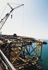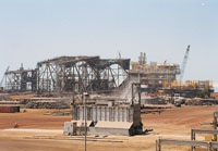


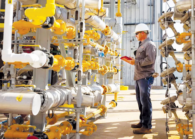


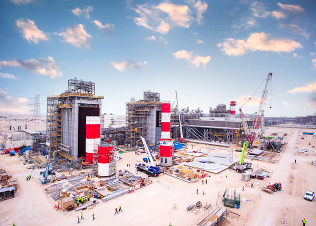


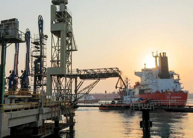


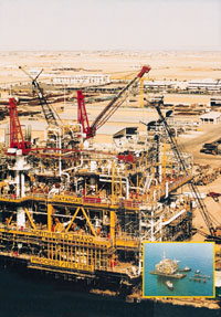
 AB Deck preparing for the entrance stage
The deve-lopment of oil and gas fields in the Gulf have demanded the installation of heavy offshore decks to meet the production requirements of those fields.
These decks vary in size and geometry according to the type of services to be provided.
A method of installing decks heavier than the capacity of NPCC's largest offshore crane had to be developed to keep pace with client requirements. The Float-over Method (FOM) of deck installation with a cargo barge was developed by NPCC with assistance from outside experts.
The first deck installed with the FOM was in the ABK field offshore Abu Dhabi.
This is a six legged gas production deck weighing 2,500 tonnes and installed in a water depth of 29m.
The second is the PU deck installed in the North Field offshore Qatar, an eight leg gas production and utilities deck weighing 6,700 tonnes and installed in 53m of water.
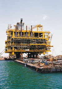
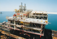
The third is the AB deck installed in Al Shaheen field, also offshore Qatar, an eight leg wellhead and process deck weighing 6,400 tonnes and installed in 61m of water.
The FOM can be done in two ways. The first, called floatover installation by barge ballasting, is by entering the installation barge inside the jacket, mooring it inside and then lowering the installation barge to transfer the deck load to the piles using ballast water only.
In the second way, floatover installation by jacking system, hydraulic jacks are used to lift the deck prior to entrance in the jacket and then used again to rapidly transfer the deck load to the piles.
Installation Procedure
Floatover installation can be performed either by ballasting only or by a combination of ballasting and jacking.
The whole installation operation is segregated into a number of different stages. These are: stage before entrance to jacket legs; after entry and mooring, but before any load transfer; partial load transfer; full load transfer and barge retrieval stage
The barge shall enter inside the jacket once the minimum clearance is achieved.
This clearance shall be due to a combination of reduced barge draft and the available tide. It is advisable to enter on a rising tide (beyond a minimum acceptable tide) since it will ensure a clearance of more than the starting clearance for a considerable amount of time to comfortably complete the entrance and mooring.
A receding tide is suitable for all other stages, reducing the time required to lower the barge, relative to the jacket. Load transfer and retrieval of barge should be planned to finish before the tide starts to rise again.
Load transfer shall be from a point on the barge which is not coinciding with the centre of buoyancy of barge, resulting in trim and heel of barge ballasting.
Special care shall be given during ballasting to adjust for this effect and keep the barge in even keel and zero trim.
Jacking System Procedure When the deck has to be transported at a low elevation on the barge due to stability constraints, jacks are employed to elevate the whole deck once it reaches the site, so that the required as-installed elevation as well as entrance clearance are achieved.
These jacks can further aid in load transfer by retracting within a duration of less than one minute.
As with the direct ballasting method, the barge should be emptied of transportation ballast before entrance, in addition to raising the deck by jacking. Jacking will bring the deck back up to the required elevation for installation, which was not possible during transportation due to stability constraints.
After entrance and mooring inside the jacket legs, the barge shall be ballasted to reduce the extreme clearance (clearance between mating parts).
This clearance shall be slightly more than the vertical motion of barge due to environmental loads to ensure that no shock loads shall be developed at this stage.
The next stage of partial load transfer involves a combination of two part jack operation combined with ballasting.
The first part of the operation shall be a 1,400mm (maximum jacks stroke) simultaneous retraction of all jacks in less than one minute without any ballasting operation.
This shall take off the extreme clearance, compress the telescopic shock absorbers, and, in the process, transfer part of the deck load to piles. Shock loads due to barge motion shall be limited to the maximum one minute duration of jack retraction. The second part of the operation is a combination of ballasting and slowly extending the jacks to the full 1,400mm, to keep the deck 'married' to the barge to prevent slamming. Jacking speed shall be synchronised with the ballasting speed so that the share of deck load taken by barge and jacket remains approximately the same.
The final stage of installation involves retracting all the jacks once again by 1,400mm in a one minute duration. This shall transfer the rest of the load to jacket as well as create a clearance between the top of the jacks and the bottom of the deck. This clearance shall ensure that shock loads due to the free barge motion shall not be severe.
To create more clearance (if required), the barge shall be ballasted more, and retrieved from under the deck.
Direct Ballasting Procedure This method is simpler compared to the combination method, since it involves only ballasting the barge down for transfer of deck load, once the barge is moored securely inside the jacket legs.
In the first stage before entrance, the barge shall be emptied of transportation ballast to create/increase clearance between the mating parts of jacket and deck; only a limited amount of ballast shall remain in barge to keep level trim and zero heel.
After entrance in-between jacket legs and mooring, barge shall be ballasted to reduce the clearance between the mating parts. There shall be no transfer of load (disregarding the barge motion) until the extreme clearance reduces to zero.
Further ballasting will compress the telescopic shock absorbers installed on the piles and ensure partial load transfer. The mating edges of deck and piles shall come in contact with each other, once the shock cells are fully compressed. The percentage load transfer at this stage will depend on the shock cell particulars. Full load transfer shall be achieved by additional ballasting.
On continued ballasting, once the deck load has been transferred to the piles from the barge, a clearance between the barge top and the deck bottom shall start to develop. Barge shall be retrieved after attaining sufficient clearance to bottom of deck.
Description of Barge and Equipment Used
Installation barge. The barge which will be used for transportation of deck as well as floatover installation, should have adequate transverse stability as well as strength to resist longitudinal bending.
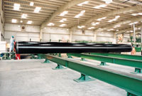
A launch barge with principal dimensions of 131.85 x 30.5 x 8 m was used to transport and floatover AB deck.
Additional 'T' girders were installed in the bottom of the barge to increase the section modulus and thus longitudinal bending strength.
This was required to resist the wave bending moment during tow in 3.5m significant waves and to withstand the sagging bending moment during entrance between jacket legs induced by the deck positioned on barge without any ballast.
Mooring System. During entrance, two stern winch lines are connected to the farthest jacket legs in a crossed manner, which are used to back the barge into the jacket during the first half of the pull and restrain the barge from moving sideways.
Once the stern of the barge crosses the third row of the jacket, the angle of the lines becomes too great to pull the barge, the bow winch lines shall then be connected to these jacket legs to pull the barge backwards.
Once the barge has reached the final location for installation, it is connected to all eight jacket legs with polypropylene ropes; the middle four ropes resisting transverse motion and the outer four ropes resisting longitudinal motion.
The barge shall be moored at the bow with three double drum winches and two double drum winches at the stern for mooring.
Ballast Control System. The barge has a built-in manifold pumping system comprising of two pumps connected to all tanks.
This internal ballast capacity of 1,500 cu m per hour was considered as a contingency and an external, manifold, centrally monitored and controlled ballasting system was installed on the barge deck.
This ballasting system consists of submersible water pumps which are directly driven by hydraulic power packs.
Nine pumps of 2,000 cu m per hour capacity were dedicated to ballasting operation and 24 pumps of 1,000 cu m per hour capacity were dedicated to deballasting operation only.
Sensors placed in each tank transmit the sounding to the control room computer, which will display the amount of ballast water, flow rate, barge draft, actual and predicted tide. In the case of floatover installation by the direct ballasting method, deballasting was normally required only before entrance into the jacket. However large deballasting capacity was provided in the event of emergency retrieval.
Fendering System. An efficient fendering system is vital to the successful execution of a deck floatover installation.
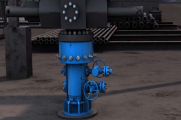
There are three sensitive locations or interfaces where fenders are required; 1) bottom of deck/substructure support connection, 2) jacket leg/barge interface, and 3) top of pile/deck legs mating.
While the deck structure is supported by the substructure in the cargo barge during transportation, a protection between the two rigid bodies is necessary.
These are called ''shock pads'', which are proven to be effective cushions for side movements of the cargo barge/deck substructure system and to allow non-rigid connection during towage.
During the entrance of the installation barge into the jacket, impact protection between the incoming barge and jacket should be provided.
These are called ''rubber V-fenders'' which are attached to the inner side of the jacket legs.
The purpose of these fenders is to absorb the dynamic impact loads caused by the prevailing weather during winching.
The third is the pile shock absorber. This is pre-installed on the top of the pile prior to deck installation. The main purpose of this shock cell is to dampen impact and to align the deck legs stabbing cone concentrically to the pile location during deck mating. These have radial and lateral stiffness to carry initial load transfer while lowering the deck through ballasting of the installation barge.
Comparison with the Lifting Method
The FOM, when compared to the traditional derrick lifting method, proves to be cost effective and time saving for topsides weighing in excess of 2,000 tonnes.
The main advantage is the elimination of a derrick barge to do the installation of the deck modules. The cargo barge, which has to be used for transportation of the deck to the field, is again used for installation. The FOM allows the full completion of the deck hook-up and commissioning onshore prior to sail away, which is not the case with lifted modules where hook up and commissioning need to be done offshore, at higher costs.
On the other hand, the FOM is a very weather-sensitive method where the limiting weather criteria should be carefully selected to suit the operational limits of the installation barge. Accordingly, this method is very much dependent on the accuracy of the weather forecasts reported for the field where the installation operation will take place.