


SOLAR gas compressors are designed for the specific needs of the oil and gas (O&G) industry in upstream and midstream applications. These applications are characterised by large changes in operation conditions on hourly, daily, seasonal, and annual time scales. Many applications are in remote areas and require extraordinary reliability and availability of all systems. Compressor drivers are usually gas turbines or, to a lesser extent, electric motors. Compressor requirements are governed by API (American Petroleum Institute) Standard 617, and Solar compressors comply with this standard.
Solar compressors use rotors of modular design. Rather than using a solid shaft with interference fit impellers, a modular rotor assembly consists of stub shafts, impellers and, if required, rotor spacers, with the assembly held together by a centre bolt. This modular design is successfully used in most gas turbines has some important advantages.
It is easy to assemble and disassemble, making restages fast and economical. It also yields a stiff shaft, resulting in favourable rotor dynamic characteristics, and allows for solid diaphragms, therefore avoiding interstage leakage problems. The API recognises Solar’s modular design as compliant with API 617 requirements. Independent studies confirm the advantages of the modular rotor over a solid shaft rotor.
The rotor design matches the Solar concept of pre-engineering and standardisation allowing for consistent, predictable aerodynamic and rotor dynamic performance. Interchangeability of many components improves spare parts logistics.
ROTOR DESIGN
Since standardised aero components are used in Solar compressors rather than a completely customised design, far more effort can be spent in careful optimisation. The optimisation process makes extensive use of three-dimensional (3-D) modeling of components, using computational fluid dynamics (CFD) tools, scaled model testing at Solar’s aerodynamic test facility, and full size testing in Solar’s closed loop test facilities. All impellers for Solar compressors are of the modern 3-D type (as opposed to so-called 2-D impellers), with three dimensionally twisted blades including inducers.
The aerodynamic design of the compressor makes use of pre-designed, pre-engineered, and pre-tested components, rather than customised stages. The advantages lie in the capability to predict and meet performance requirements. Modern computational tools, together with expanded test capabilities, have been used to design compressor stages with high efficiency and a wide operating range by carefully optimising each individual impeller and diffuser, together with the inlet system and the discharge volute. The superior performance of Solar pipeline compressors (C40, C45, C65, C75 and C85) and production compressors (C16, C33, C41, C50, C51, C61, and others) has been verified in factory tests and, more importantly, in many instances under real conditions in carefully instrumented site performance tests. In all cases, special emphasis is on achieving high flexibility to meet the ever changing operating conditions of upstream and mid stream oil and gas applications.
Product advances have been made by means of evolutionary changes. When the C401/2 compressor was introduced, it used new aerodynamic components. The mechanical system, however, was largely adapted from the successful C16 and C33 compressors. The C65 and C45 pipeline compressors are geometric scales of the C40 pipeline compressors. In addition, the C45 compressors use identical bearing and seal systems as the C40M multi-stage machines. In turn, when the C51 was introduced, many features were adapted from the C40M, and the impellers were designed based on the experience of this machine, as well as the pipeline compressors. The extremely positive operating experience with the C51 compressor subsequently led to the introduction of linear scales of this machine: the C41 and the C61.
Solar’s compressors continue to gain increased acceptance at higher discharge pressure levels. C16 compressors now operate successfully at discharge pressures in the 3,000 to 4,000 psi range. This increase in pressure capability was a deliberate process of small steps to gain increased operating experience under increasingly challenging rotordynamic operating conditions and careful closed loop testing.
The process was complemented by continuous improvement in dry and wet gas seal technology, and bearing technology.
All compressors use the same modular rotor designs introduced by Solar in the 1960s and used in over 5,000 Solar gas compressors. Solar’s compressors successfully help users worldwide, offshore and onshore, in applications like gas export, gas boost, gas gathering, gas lift, gas reinjection, pipeline transmission, and gas storage.
The modular rotor design allows for a vertically split stator, thus avoiding large stator deflections at high pressure operation. Solar uses vaneless diffusers on all models to maximise the operating range of the compressors. The compressors feature dry gas seals with intermediate labyrinths, the journal and thrust bearings are of the tilting pad design. Thrust balance is achieved with a balance piston with labyrinths on the rotating part and abradable seals on the stationary part. The bundle removal can be performed in the field using tools designed for the compressor. The bundle contains the aerodynamic components, as well as the bearings and seals.
SOLAR COMPRESSORS
Solar’s heavy investments in state-of-the-art test facilities allow rigorous tests of centrifugal gas compressors, both during development as well as to meet customer requirements.
The multistage compressors, for example, have been subjected to a rigorous rotordynamic test programme, taking advantage of the Gas Compressor Test Facility with its 20,000 horsepower (hp) driver, and the capability to test at discharge pressures of up to 3,000 pounds per square inch (psi). The tests were performed both with inert gas (nitrogen) and natural gas. One of the goals was to determine the stability limits of different configurations, which are then used as application limits for the compressor.
The test programme included the tests for the longest available rotor, as well as tests of different bearing configurations, including squeeze film damper bearings. A magnetic exciter was used to determine experimentally the damping of the rotor, that is, the log decrement, at different operating conditions.
The art of designing a gas compressor constitutes the effective blending of aerodynamic desires with rotordynamic and structural restraints. Important conditions are imposed by the requirement for stable rotordynamics and structural integrity. Additionally, the manufacturing process and its inherent strengths and limitations have to be taken into account.
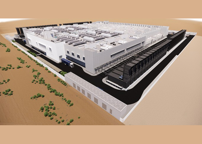
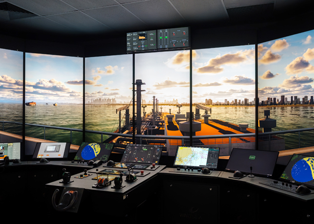
Equally important to a superior design is the capability to support the machinery once it is in the field. Solar Turbines has excellent support capabilities with worldwide service centres. This includes a new service facility in Dubai, with field support offices, a machinery management centre for remote monitoring and diagnostics for units in the Middle East area, as well as training facilities.


