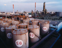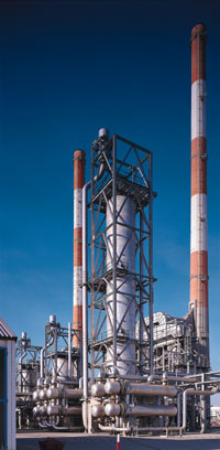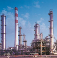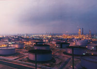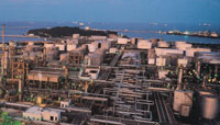
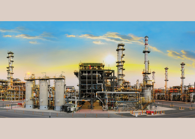


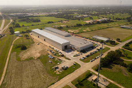

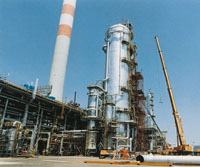
An upgrade at the crude distillation tower of Rabigh refinery has boosted sustainable capacity by at least 30 per cent with a low investment, writes Abdullah Al Subaiyel. Following major modification of the crude distillation tower at Rabigh refinery, the unit is set to be one of the largest crude distillations units (CDU) in the world at 425,000 barrels per day (bpd).
The crude distillation tower was designed to process 325,000 bpd of both Arabian Light and Arabian Medium crude crudes with an extra 10 per cent over design limits. The distillation tower is split into two towers, C-01 A & B, due to high capacity and static load.
The first tower, C-01 A, is fed with crude and produces fuel oil (FO), heavy gas oil (HGO) and light gas oil (LGO).
The second tower fractionates light vapour producing kerosene and whole naphtha. Both towers were revamped, section by section, according to limitations in each area.
Prior to the upgrade, the entire crude unit was subjected to two capacity test runs with Al feed to identify major limitations in all equipment and especially the crude distillation tower.
Based on the test run results, it was concluded that a minor investment to upgrade the tower internals would achieve both the yield improvement and the internal hydraulics limitation debottlenecking.
A leading tray manufacturer was asked to study the test run results and recommend a long-term low-investment solution for the 400,000 bpd sustainable capacity.
Out of three proposals, Rabigh refinery process engineers selected the most economical one, based on economics incentives and low investment cost.
Their proposal was to upgrade the tower internals with high-capacity trays.
Tower internals upgrade
C-01 B
Major upgrade changes took place in the light fractionation section in the distillation tower C-01 that has an inside diameter of 7,700 mm and 35 valve trays. The following was completed:
C-01 B Top Section (trays 33-35): based on the 400,000 bpd test run, the high jet-flooding rate exceeded 85 per cent of the recommended rate. It was recommended to replace the three old four-pass valve trays with high-capacity trays, maintaining the same 915 mm spacing.
C-01 B Middle East Fractionation Section (trays 13-32): the study recommended replacing 20 old two-pass valve trays with high-capacity four-pass trays, maintaining the same 760 mm tray spacing. Minor tray support modifications were made to handle the extra physical load.
C-01 B Kerosene Section (trays 10-12): the conventional packing or normal valve trays solution was unsuitable to handle the high loading rate in this section.
However, new high-capacity-tray advanced technology was the solution to this limitation. These three old four-pass valve trays were replaced with new-technology trays with the same 760 mm tray spacing in that section. Major internal changes, considering tower shell dimensions, were made in this section. A new liquid distributor was added on top of tray No. 12
C-01 B Lower Section (trays 1-9): similar to the top section, the same high jet-flooding limitation exceeding 85 per cent existed at this 400 ,000 bpd rate.
The entire nine old two-pass valve trays were replaced with nine new four pass high-capacity trays at the same tray spacing of 760 mm. During the 400,000 bpd capacity test run, this section encountered high liquid levels due to rashing of vapors traffic in that area.
C-01 A
C-01 A tower consists of 42 valve trays with inside diameter of 9,500 mm.
Modifications were made to the tower internals in the top section, the LGO pump-around section and the HGO pump-around section.
C-01 A Top Section (trays 40-42): the top section of C-01 A did not encounter a flooding problem. However, the vapour velocity was very high through the three two-pass valve trays, which resulted in severe entrainment of vapours with liquids. This was solved by increasing the number of valves in each tray by 25 per cent using existing active panels. This modification reduced the vapour velocity to an acceptable level, eliminating the entrainment in upward-moving vapour.
C-01 A LGO P/A Section (trays 37-39): similar to the naphtha P/A section the LGO P/A section was heavily loaded, exceeding the recommended jet flood of 85 per cent. The three four-pass valve trays were replaced with high-capacity trays at the same tray spacing. Only down-comers were slopped to accommodate these changes.
C-01 A HGO P/A Section (trays 12-14): partial tray replacement was recommended in this section by partially replacing some panels with others containing 25 per cent additional valves to ease the vapour flow and minimise the entrainment of vapours in that section. Three four-pass trays were replaced with high-capacity trays.
C-01 A Section trays (1-5), (6-11) & (15-36): remaining fractionation sections of the C-01 A tower remained unchanged because distillation criteria were within limits even at the 400,000 bpd new capacity.
The Side Strippers C-02, C-03 & C-04: following the same analysis, the study revealed high jet-flood rates exceeding the 85 per cent value in the three side strippers; the kerosene stripper C-02, the LGO stripper C-03 and the HGO stripper C-04. These strippers used to contain six two-pass valve trays each.
All the side strippers' valve trays were replaced with high-capacity trays, maintaining the same tray spacing of 610 mm for both the kerosene and the HGO side strippers and 710 mm for the LGO side stripper.
The 400,000 bpd upgrade study was based on actual visible revenue to the refinery. The upgrade design was limited to eliminate the limitations and to improve product quality toward high-value products.
The refinery margin has improved by about 0.15 cent per barrel.
Certain equipment and heat exchangers were reconfigured to improve the DP across the preheat exchangers, parallel trains, so the unit upgrade was enhanced to eliminate all the debottlenecks in the unit.
Based on the success achieved so far, the following innovative ideas were proposed:
Winter Capacity Test Run
This test run was performed five months after the unit stabilisation following the upgrade work.
Unit capacity was tested in the winter for maximum sustainable limits.
It was found that the feed could be boosted to 425,000 bpd, maintaining all products within specifications and without jeopardising the unit's main equipment performance.
The test run was ceased at 425,000 bpd due to limitations in the crude heater and the top reflux of C-01 B.
However, the tower may work efficiently at 450,000 bpd. Refinery experts are addressing these limitations.
Heavy Naphtha Draw
Based on a study performed in 1996, a side stream from the naphtha P/A was checked for specifications and results revealed excellent specifications as a direct feed to the platformer unit.
The project was executed last year to produce 20,000 bpd of heavy naphtha. Minor modifications were made, including a new trim cooler and piping modifications in the tank farm area in addition to control loops.
The heavy naphtha has an extra value over the whole naphtha by $0.3 per barrel.
Based on encouraging results and objectives achieved in this special fractionation tower upgrade more ideas were proposed, including upgrading the tower toward 500,000 bpd.
This will require substantial effort and such an upgrade will require a major investment and will be judged on economic incentives.
The 500,000 bpd crude distillation unit upgrade is being considered in the next operating plan.
Abdullah Al Subaiyel is superintendent of Rabigh refinery operations. The paper first appeared in the Saudi Aramco Journal of Technology.