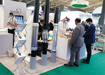
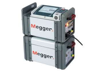
 Megger’s DELTA 12-kV insulation diagnostic system
Tap changer failures can come at a cost to utilities and, therefore, the importance of its reliability cannot be over emphasised.
The on load tap changer (OLTC) is the only moving part connected to the transformer windings, and as such is the most susceptible to failure.
Taking a transformer off the system to investigate an internal problem with a tap changer is an expensive exercise; therefore, it is in every utility’s interest to carry out condition assessments of their tap changers to help detect developing faults at an early stage.
According to a CIGRE survey, about 27 per cent percent of failures in large transformers over 100 kV are due to tap changer failures.
 |
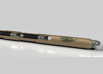
IDAX DFR test instrument |
The tap changer allows input or output voltage to be higher or lower (as may happen when a power company system changes or load increases).
The voltage changes involve a mechanical movement of a contact from one position to another. It is this contact that needs to be checked by way of its resistance. The contact may go bad for several reasons:
• Misaligned when manufactured causing insufficient surface contact; full load current overheats contact surface causing it to burn.
• Current passing through contact exceeds full load rating.
• Tap changing operation not ‘make-before-break’ creating internal arcing of the contact surface.
 |
TRAX multi-functional tester for transformer and substation equipment |
• An off-load tap changer is switched while on load. Thus a contact surface becomes pitted and uneven.
Tap changers, which have not had positional changes over long periods of time, are subject to bad initial contact resistance when changing tap position and hence the failure, which can be catastrophic.
CONTACT DEGRADATION
An OLTC has sets of contacts that switch different currents at different recovery voltages.
For example, the main contacts of the arcing switch are designed to transfer the load current to the transition contacts.
The arcing contacts of the arcing switch are designed to break the load current and the circulating current.
In contrast, the contacts of the tap selector and the changeover selector are not designed to switch current. Therefore, these sets of contacts wear differently.
Changeover selector contacts (including tap selector contacts) do not wear as fast as arcing switch contacts that wear due to the switching of load currents.
These contacts will not switch significant currents but can show pitting of the contacts and the development of pyrolytic carbon.
This contact degradation is not due to the arcs caused by switching the current but by a long-term overheating process.
STATIC WINDING RESISTANCE MEASUREMENTS (WRM)
The most common diagnostics test for tap-changers is to perform winding resistance measurements (Figure 1).
 |
Figure 1: WRM/tap, diverter design (old/aged condition) |
WRM is normally performed for each tap in the same way as an individual winding without taps.
A suitable test current is injected through the winding and the resistances for each tap are measured sequentially as the tap changer is stepped through its positions. The results are typically presented as a graph or table with resistance values for each tap.
Resistance changes between taps should be consistent with only small deviations between different tap position changes. An example showing deviations between taps is shown in Figure 2: Red phase is ‘OK’; Blue phase is ‘Questionable’.
DYNAMIC RESISTANCE MEASUREMENT (DRM)
The high failure rate of OLTCs emphasises the need to understand tap changer degradation.
 |
Figure 2: An example of DRM resistance graph results obtained |
There exist different degradation mechanisms (electrical, mechanical, thermal and chemical), and the different types of defects in OLTC can be defined from the DRM measurement results.
The advantage of DRM over static WRM measurement is the ability to obtain more detailed information and locate the fault inside the OLTC. It can be done fast as there is no need to wait for stabilisation.
The location and shape of the deviation in the DRM graph can define the problem and its severity, which could include increased contact resistance, interrupted test current, or internal degradation of OLTC.
Some problems can be noticed by generally looking at the overlay results. However, the defectiveness of, for example, a particular transfer switch on particular phase can be found by analysing DRM graphs in details.
Some of the problems that can be detected by DRM are contact coking, contact timing problem, and damaged transition resistor.
Increased contact resistance, open contacts and deviation switch time are the situations that can define a problematic OLTC. A further explanation shows:
• Increased contact resistance can be due to contact degradation. Some situations like often switched contacts are less prone to the contact coking.
• There are boundaries for OLTC switch time interruptions. Above the maximum boundary of the open contact, discontinuity is detected. Problems can be localised depending on the interruption time.
• The open contact is suspected when the current drop happens below 10 per cent of the applied current.
The contact resistance of the degraded OLTC is highly current dependent. Therefore, the current choice can have effect in the fault detection: Low test current measurement is more sensitive to the degradation; and although with higher current, the measurement results are more reproducible, but it is less reliable.
It is recommended to do the WRM measurements with 1-10 per cent of the nominal current.
For DRM there is no need to wait for stability as in WRM. Therefore, it doesn’t hurt to do the measurement with lower current.
When the DC current exceeds the knee point magnetisation current, the core gets saturated, and inductance can be reduced as much as possible.
It can be harder to detect OLTC on the delta connection side as there is an alternative current path that deludes the interruption.
In case a problem is detected in the DRM results, the repeatability of the can be checked by further measurements.
A few times of switching can also help to remove any coking on the contacts. It is wise to check how the results are affected by different current levels. Defective springs can also lead to the increased switching time.
DYNAMIC CURRENT MEASUREMENT
The moment a tap changes, a short drop of current can be detected.
Interruptions during changes in the tap changer can lead to different ripple and slope values in the current for a healthy or malfunctioning tap changer. Usually, the problematic one results in larger ripple and slope.
The condition of the transition resistance and mechanical faults can be assessed.
Dynamic current measurements are pending test current. If the test is performed at a current level below saturation level, the inductance in the transformer winding is high and smooths the current change. If the test is performed at a current level at or above saturation level, the inductance is low and current level change will be higher.
A method to reduce transformer inductance when performing TC measuremewnts is to short-circuit the not-tested corresponding LV (or HV) windings.
This action is principally ‘replacing’ the inductance of the winding with the short-circuit impedance. Inductance is greatly reduced and changes in current can be measured more precisely.
RESULTS
Alternating contact resistance can be due to:
• The problem in one set of diverter switch or tap selector contact.
• Higher resistance of any special tap compared to the others.
• Resistance deviation when change over selector is operated
• Broken spring.
• Irregular transition time can be due to the problem with transition resistor.
• Open contacts.
• Service-aged coarse changeover selector. The contact resistance increases just before the operation of the arcing switch and lasts several seconds until the operation of the arcing switch.
DRM ON VARIABLE SHUNT REACTOR
The magnetising current in reactors is equal to the load current, which can be in the range of 100-300 A, and the measurement current should not exceed that.
Additionally, it is not allowed to run the full load due to the thermal effect.
Resistor-type OLTC can be used and defines the resistance values together with reactor inductance defines the time constants, including the arcing time, the time when transition resistors are connected, and the time when the next tap is connected
























.jpg)


