


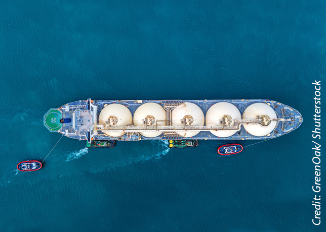


As the challenge of marine fuel availability continues, LNG is being proposed as a fuel option that vessel owners might use in combination with technological and operational improvements to meet IMO 2030 CO2 reduction targets, says a report by the American Bureau of Shipping
The adoption of the ‘Initial International Maritime Organization (IMO) Strategy on Reduction of Greenhouse Gas (GHG) Emissions from Ships’ through a resolution in April 2018 demonstrates IMO’s commitment to support the Paris Agreement.
The IMO strategy includes initial targets to reduce the average carbon dioxide (CO2) emissions per "transport work" by, at least, 40 per cent by 2030, aiming to pursue 70 per cent reduction by 2050; and an ambition to reduce the total annual GHG emissions from shipping by, at least, 50 per cent by 2050.
Technical approaches, operational approaches and alternative fuels may be used to achieve these goals.
LNG as a fuel is one of the options that an owner might use in combination with technological and operational improvements to meet Initial IMO 2030 CO2 reduction targets, says a recent report entitled 'Sustainability Whitepaper: LNG As Marine Fuel' by the American Bureau of Shipping (ABS).
LNG AS FUEL FOR GHG REDUCTION
Liquefied natural gas (LNG) is a relatively mature low-carbon fuel, comprised primarily of methane and may be a viable option to meet the 2030 emission reduction goals.
In a comprehensive approach, the first step would be to benchmark where an owner’s fleet is currently in its emissions reduction plans. Then look at the intended operating profile of the vessel/s and determine how an LNG fueled vessel would fit into the company’s plans and what savings they could expect.
The operating profile impact is not to be underestimated, as depending on the fuel system selected a vessel may not get the expected 20 per cent reduction.
Burning of natural gas in boilers to control tank pressure has been used as a convenient means of controlling LNG tank pressures and temperatures and maintain them within acceptable limits.
However, this excess consumption simply to control and maintain pressures affects the overall carbon footprint.
The type of containment system used, boil-off gas (BOG) management system in place and combustion process adopted have an impact on total GHG emissions.
CHARACTERISTICS OF LNG
LNG is a mixture of several gases, in liquid form, principally composed of methane (CH4), with a concentration that can vary from 70 to 99 per cent by mass, depending on the origin of the natural gas.
Other hydrocarbon constituents commonly found in LNG are ethane (C2H5), propane (C3H8), and butane (C4H10). Small amounts of other gases, such as nitrogen (N2), may also be present.
Natural gas reserves are significant, with the International Energy Agency (IEA) estimating reserves at current usage rates (January 2011) are over 250 years.
When liquefied at approximately -162 deg C, the volume required for natural gas is reduced to about 1/600th of that required when in the gaseous state. In this condition, LNG is stored in tanks where the heat ingress leads to the generation of boil-off gas (BOG).
The BOG is consumed by the engines or is re-liquefied in order to maintain the LNG tank pressure within acceptable limits. The LNG saturation vapour curve and its effect on bunkering is to be fully comprehended to improve bunkering.
Both marine slow-speed two-stroke engine manufacturers, MAN Energy Solutions and Winterthur Gas & Diesel (WinGD), offer DF internal combustion engines.
However, each manufacturer has selected a completely different combustion process for when the engine operates in gas mode.
The two different gas mode combustion concepts are low-pressure (LP) gas engines using the Otto cycle and high-pressure (HP) gas engines using the Diesel cycle.
The WinGD LP DF engines (X-DF) utilise the Otto process in gas mode and the conventional diesel process when in oil mode.
The MAN HP DF engines (ME-GI) use the diesel combustion process in both oil and gas modes.
For both concepts, the gas is ignited by a pilot injection of liquid fuel from the conventional fuel injection system, or a dedicated pilot fuel system.
The point during the combustion cycle where the gas is injected dictates the required gas supply pressure.
The WinGD X-DF is designed to operate at a gas supply pressure of up to 13 bar, and the high-pressure MAN ME-GI uses gas delivered by a direct injection system at approximately 300 bar.
The two different designs lead to different combustion concepts, Otto cycle for the X-DF and diesel cycle for the ME-GI, and therefore have different performance and emissions characteristics.
A recent announcement by MAN involved the development of their low-pressure DF engine, ME-GA.
Overall, the suitability of a specific concept, or engine type, to a ship is very much a case-specific decision.
For some, it may simply be that they are not comfortable with HP gas or the increased complexity and cost associated with HP fuel gas supply systems.
For others, it may be the concerns with Otto cycle being sensitive to a number of operating parameters (methane number, ambient conditions), or the GHG impact of methane slip.
DESIGN CONSIDERATIONS
For LNG fueled ships, the main systems to be accommodated in a design concept that are different, or additional, to conventional ship designs are the LNG fuel containment system, associated LNG bunker station and transfer piping, a fuel gas supply system, the double-wall fuel gas distribution piping, gas valve unit, gas consumers, nitrogen generating plant, vent piping systems and mast(s), and for some LNG tank types, additional equipment for managing tank temperatures and pressure.
The protective LNG tank location criteria can be based on a deterministic approach considering tank volume or a probabilistic method.
The International Code of Safety for Ships Using Gases or other Low-Flashpoint Fuels (IGF Code) provides a third alternative, where the ship’s hull is specifically designed and reinforced in the way of the LNG tank, therefore minimising the impact from a collision and so allowing the tank located closer to the ship’s side shell.
The probabilistic method requires the input of a number of ship and tank parameters to calculate the required "fCN" value, which must be below 0.04 for cargo ships and 0.02 for passenger ships.
The "Emergency Shutdown (ESD)-Protected machinery space" concept introduces additional measures to provide an equivalent level of safety to the conventional non-hazardous machinery space.
Application of the ESD-Protected machinery space has been limited so far because of the growing availability of engines that can be supplied meeting the double barrier criteria and perhaps because of the additional vessel complexity and cost that meeting the ESD machinery space concept brings.
The non-hazardous machinery space concept is based on the use of double barriers for all gas-containing components such that a failure in a single barrier cannot lead to a fuel gas release into the space.
The nonhazardous machinery space also shows the GVU room. This may be a separate space outside of the machinery space, or may be a GVU unit, which is a self-contained unit that is essentially an extension of the double barrier piping system and may be located within the non-hazardous machinery space.
• Fuel storage: There are four main types of LNG tanks, namely independent tank types A, B and C, and integrated membrane tanks.
Types A, B and membrane are low pressure, nominally "atmospheric" tanks, whereas Type C are pressurised tanks.
Type A, B and membrane tanks require a secondary barrier to protect in case of leak from the primary barrier.
Type A and membrane systems require a full secondary barrier. Type B requires a partial secondary barrier since these are designed using advanced fatigue analysis tools and a "leak before failure" concept, for which small leaks can be managed with partial cryogenic barrier protection and inert gas management of the inter barrier space. And Type C tanks are designed using pressure vessel code criteria and conservative stress limits; therefore, they do not require a secondary barrier.
• Boil-off gas: For GFS, the amount of BOG available in certain instances might not be sufficient to sustain the ship’s power demands at maximum continuous rating, so the fuel gas supply systems need to force vapourise the LNG into conditions suitable for the engines.
In some cases, the designers may prefer to force vapourise LNG and send it to the main engines because it might be cheaper and more efficient to boost pressure on LNG and vapourise it on a high-pressure vapouriser rather than use a compressor.
But the ship will still need to manage the BOG and LNG tank pressures at all times, including times where there is no gas consumption by propulsion related consumers, which can lead to many potential combinations for fuel supply and BOG management equipment.
• Fuel gas supply systems: The purpose of the FGSS is to deliver fuel to the engine or consumer at the required temperature and pressure.
For gaseous fuels using cryogenic/pressurised liquefied storage, the fuel may be pumped or pressure fed, directly in liquid form, such as LNG, from the tank and vapourised to a gaseous state for the consumer, or supplied in combination with the use of compressed gas from the natural tank BOG.
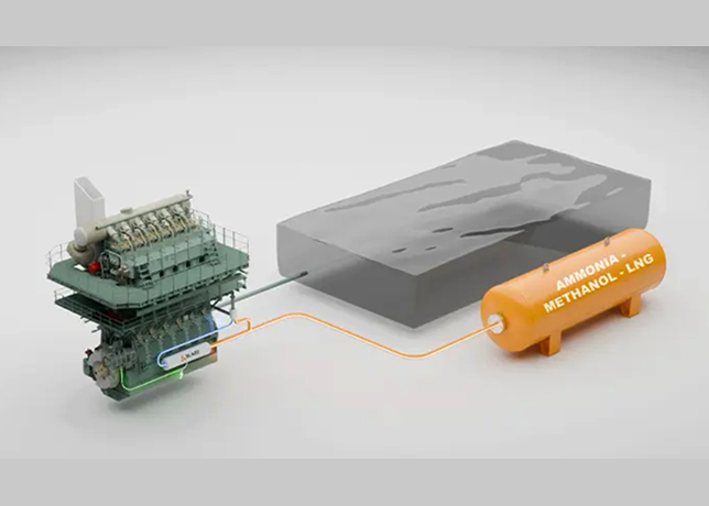
• Dual fuel engine conversion: Operation with gas as fuel requires specific FGSS to feed the DF engine with gas at the required pressure and temperature.
In addition, the main DF engine, the components of which are generally based on the conventional diesel engine design, require some key base engine components in order to operate in gas mode.
Furthermore, the ability of a Diesel engine to be easily converted to a DF engine in the future may also be an important decision, for example, if an owner is selecting a "Ready" notation in preparation for converting the ship to burn natural gas at some point after vessel delivery.
• Bunkering system: Bunkering is to be considered at the beginning of a design project to ensure optimum design. If during the design stage the trading route is known and the potential bunker supplier along the route identified, measures/contracts can be established to ensure the parameters of the LNG vessel during bunkering and the supplier/bunker vessel are aligned and procedures of bunkering standardised.
If trading routes and suppliers are unknown during design stage, then it might be beneficial to increase the equipment limits on the ship to ensure issues arising from bunkering are handled correctly.


