


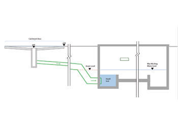
 Figure 1 … a typical OWLS schematic
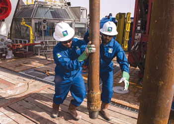
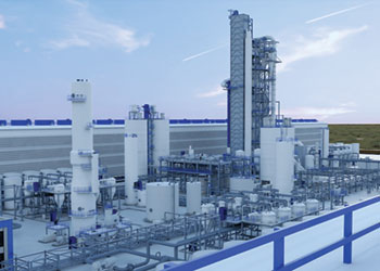
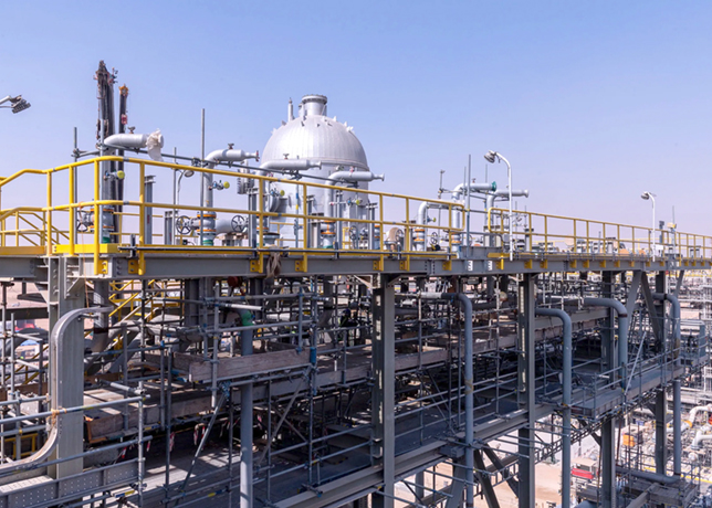
Aramco researchers Talal AlShalan* and Nicholas Morrison found a hybrid design utilising a storage buffer to significantly reduce overall pump capacity and downstream facilities in the oily water lift station at Tanajib Gas Plant
Operators at the Tanajib Gas Plant (TGP) wanted a reassessment of the typical oily water lift station (OWLS) design to reduce the magnitude of construction and maintenance activities associated with the oily water system (OWS).
They wanted a design, which achieved the degree of optimisation required for a large scale facility, which had excessive pumping capacities and a large downstream system.
 |
|
AlShalan and Morrison ... looking for optimised design |
The OWLS design was, therefore, analysed using a storage buffer, and surcharging the OWS to reduce the required pumping capacity.
• Plot location and bypass requirement: Both the oily water and clean stormwater (CSW) drainage systems are underground-piped networks.
Operations also required that the OWLS come with a bypass to divert flow from one OWLS to another in case of a fire scenario or moderate storm during turnaround and inspection (T&I) activities.
The OWLS for different units were, therefore, ‘paired’ and located in proximity to each other to be able to be connected with a bypass.
Although minimising the number of lift stations within a facility is desirable, this needs to be achieved within practical limits.
The TGP lift stations collect from large areas requiring a colossal plot area. The depth of the OWLS is also significant—at around 10 m deep.
It is beneficial to avoid large excavation and construction works within the water table to mitigate any dewatering activities.
• Hold up time versus high flow pump capacity: As per the requirements, the minimum volume of a lift station must be sufficient to ensure that the pumps run for a minimum of 15 minutes, with no limitation on the maximum pump run time. From a pump design perspective, the fewer times the pump starts and stops during operation, the better.
The maximum working water level inside the OWLS is limited to the invert level of the incoming pipe as not to impede the incoming flow, as illustrated in Figure 1.
 |
|
Figure 2 … a typical surcharged OWLS schematic |
For the stormwater case where the water is effectively clean, by increasing the storage volume in the OWLS and using it as a buffer, the stormwater can be retained for a duration to reduce the overall required high flow pump capacity.
Fewer pumps also mean reducing the maintenance activities required during operation. There is, therefore, significant capex and opex avoidance by utilising a stormwater buffer in the OWLS.
Although the lift station already has some design redundancy by requirements with the provision of a standby pump, having an additional storage volume in the lift station also adds to the redundancy of the overall OWS network where stormwater can be retained.
• Surcharging the system: The TGP project also studied surcharging the OWS network to further optimise design. This design requires elevating the working water level in the lift station above the invert of the inlet pipe, as illustrated in Figure 2.
As per the requirements, this impedes the flow in the inlet, which was not accepted. The concept, however, could be technically feasible, as explained below.
 |
|
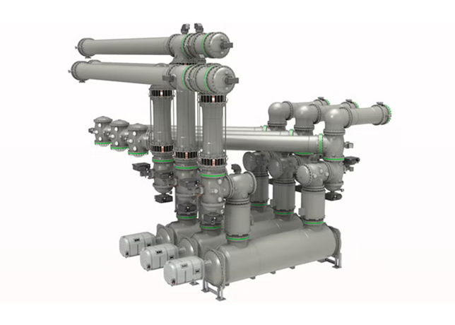
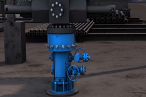
Figures 3 and 4 … 3D model view of OWLS |
For the TGP project, the stormwater flow depth for both the CSW and OWS is limited to 2/3rd of the pipe depth.
As per the requirements, the drainage system should also be designed to avoid flooding of surrounding areas in a 1/100-year storm. For this to occur, the flow would have to surcharge and backup until flowing over the high point paving of the catchment area.
There is a huge volume in the upper portion of the lift station, the piped network itself, and the volume in the sloped catchment areas up to the High Point of Paving (HPP).
With the help of drainage software, it was calculated that there was sufficient volume in the piped network to contain the full volume of stormwater without the water even rising above the low point of paving, that is, contained completely underground.
In the surcharged scenario, the max working water level rises above the inlet invert level.
 |
|
Figures 3 and 4 … 3D model view of OWLS |
Simulations showed that in the worst condition, the minimum velocity of the flow in the inlet was 0.75 m per second, which is still self-cleaning per other operating and international standards.
If adequate hydraulic simulations are undertaken, surcharging the system could be technically acceptable if suitable minimum flow velocities are achieved.
The size of the buffer volume should be limited to achieve minimum flow velocities and empty the stormwater with a reasonable timeframe.
By utilising even more storage capacity of the lift station and the piped network, the system (pump capacities, headers, power consumption, lift station depth, etc) could potentially be further optimised with additional CAPEX/OPEX benefits.
• Explosion relief panels (ERP): One concern for such a large OWLS design is the possible accumulation of flammable gas/liquids in a large, enclosed pit within the process areas of a plant.
Although the system is vented and not permitted to drain flammable effluent to the OWLS, reports have shown that, at times, this has accidentally occurred at existing facilities and has resulted in explosions/deflagrations in the OWLS.
The TGP project incorporated ERP in case such an accidental deflagration event could occur.
ERP panels are thin metallic domed vent covers designed to rupture when internal pressures rise due to deflagration.
During design development, when calculating the required area against National Fire Protection Association (NFPA) standards, the amount of vent area almost covered the entire surface area of the OWLS.
To limit the amount of ERP vent area, the chambers were segregated with an underflow baffle wall with liquid seal to separate the vapor spaces between oily and deluge chambers.
The number of panels for this chamber were also reduced using a Computational Fluid Dynamics (CFD) study instead of the standard NFPA formulations.
The risk of deflagration was significantly reduced to avoid the requirement of ERP in the large deluge chamber, as shown in Figures 3 and 4.
• Conclusion: Using a storage buffer in the OWLS for stormwater flow can have significant capex/opex benefits for large oil and gas facilities with significant stormwater runoff.
Meanwhile, ERPs proved to be an additional safety feature to protect from accidental spillage and deflagration.
And segregating the vapour spaces of the oily water and deluge chambers limited the extent of deflagration and number of ERP’s.
Overall, the TGP project implemented a cost-effective design solution for OWLS with additional safety features beyond minimum standard requirements.
• Talal AlShalan is a project engineer with extensive experience in the projects/programmes lifecycle and with over 10 years’ experience at Saudi Aramco. He has worked as project engineer, planning engineer and estimating engineer in various projects in oil and gas, infrastructure and housing. AlShalan has a Bachelor’s in Civil/Hydraulic Engineering from King Saud University and an Executive MBA from Prince Mohammed Bin Salman College.
• Nicholas Morrison is a consultant civil/structural engineer with over 20 years’ experience in design, construction and project management of projects in oil and gas, mining, infrastructure and commercial building sectors, both greenfield and brownfield. Morrison holds a BE degree in Civil engineering from the University of Auckland, New Zealand.
By Abdulaziz Khattak