


With a dedicated carbon capture solution portfolio, Sulzer addresses the specific requirements of various solvent-based technologies at scale, Dr Rafic Traboulssi, Strategic Business Development, tells OGN
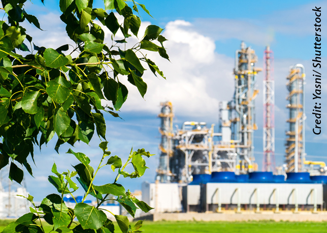
As countries strive to achieve net-zero carbon emissions by 2050, a key pillar is the defossilisation and decarbonisation of energy systems and chemical production pathways.
There is broad consensus that carbon capture, utilisation, and storage (CCUS) is an essential part of a diversified solution portfolio required to achieve net-zero.
By 2050, it is estimated that between 4.21 and 7.62 gigatons of CO2 will need to be captured annually.
Companies worldwide are, therefore, increasingly integrating carbon capture into their corporate strategies.
Sulzer’s innovations in the field of carbon capture, such as MellapakCC™, AYPlus™ DC, and MellaTech™, are designed to optimise total cost of ownership (TCO) and enhance process reliability, key enablers for the cost-efficient, large-scale deployment of carbon capture.
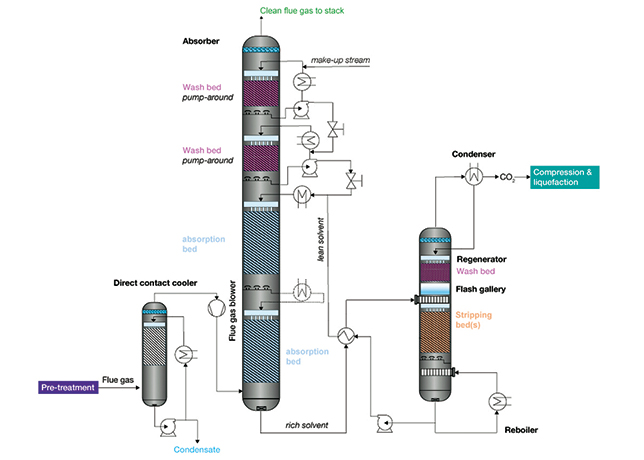 |
Figure 1 ... carbon capture plant process |
POST-COMBUSTION CARBON CAPTURE PLANT
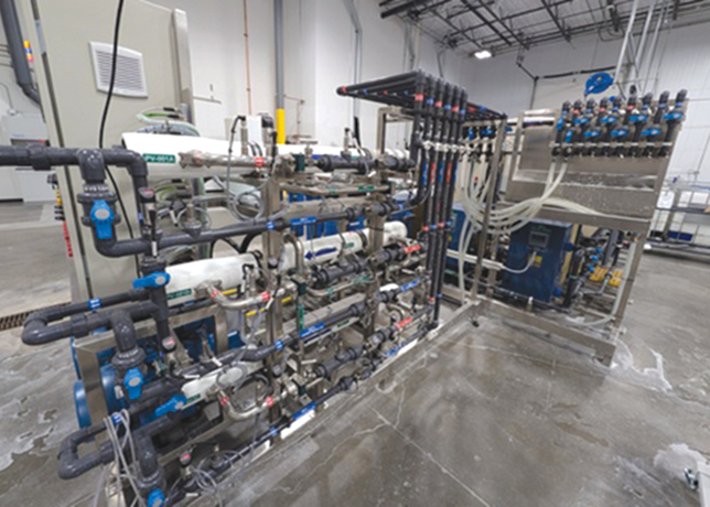
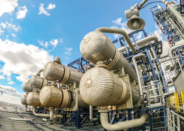
A carbon capture plant consists of three main columns: the direct contact cooler (DCC), the CO2 absorber, and the CO2 stripper (Figure 1); and Sulzer offers unique solutions for all three sections of the process.
• Direct Contact Cooler (DCC): The pre-conditioned flue gas enters the DCC (also called Quencher) at an elevated temperature. There, it is cooled slightly above the cooling water temperature. A pump-around system ensures optimal liquid loading for efficient heat and mass transfer.
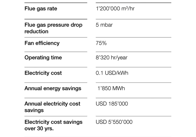 |
Table 1 ... Savings of flue gas blower - 750 MW NGCC |
Sulzer offers compact, cost-effective DCC designs with full process guarantees for performance, operability, and reliability.
The flue gas blower (booster fan) located immediately downstream is a long-lead, high-impact item affecting both capex and opex.
Its power consumption is directly related to the total pressure drop across the DCC and CO2 absorber, making it a major opex contributor.
Table 1 (750 MW NGCC case study) shows the significant reduction in blower energy consumption achievable by lowering flue gas pressure drop. A reduced pressure drop also decreases blower size, footprint, and capital cost (Figure 2).
 |
Figure 2 ... Flue gas blower capex savings versus pressure drop reduction |
• CO2 absorber: The CO2 absorber is the largest column in a carbon capture plant, reaching heights of 50-60 m. The CO2 removal from flue gas at near-atmospheric conditions presents key challenges, such as a low CO2 partial pressure limiting the thermodynamic driving force, making efficient solvents and mass transfer equipment critical.
Additionally, solvent volatility may cause losses and emissions, while flue gas impurities and high temperatures can lead to solvent degradation, aerosol formation, foaming and fouling.
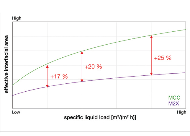 |
Figure 3 ... effective interfacial area of MCC and M2X versus specific liquid load |
• CO2 absorption: As shown in Figure 1, the CO2 absorption section typically features two to three packed beds, depending on the capture target, process configuration, and solvent properties.
Inter-cooling between beds can be applied to control temperature rise from the exothermic reaction, shifting vapour-liquid equilibrium to improve CO2 absorption and enable higher solvent loadings, which is especially beneficial at elevated flue gas CO2 concentrations.
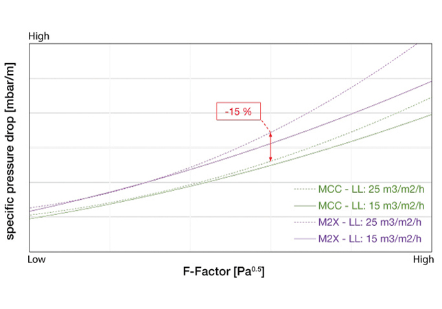 |
Figure 4 ... specific pressure drop of MCC and M2X versus F-Factor at 15 and 25 cu m (sq m h) |
Pressure drop across the tall absorber is dominated by the absorption section. Structured packing has become the industry benchmark, outperforming trays and random packing with higher capacity, efficiency, and lower pressure drop. Despite this, pressure drop remains a critical opex driver.
Sulzer developed the MellapakCC™ family to address this challenge, delivering the lowest pressure drop for a given CO2 absorption efficiency in the industry.
This step-change innovation significantly reduces both opex and capex.
MELLAPAKCC VERSUS MELLAPAK 2X
Mellapak™ 2X is a well-established packing type in CO2 absorption that serves as a reliable benchmark.
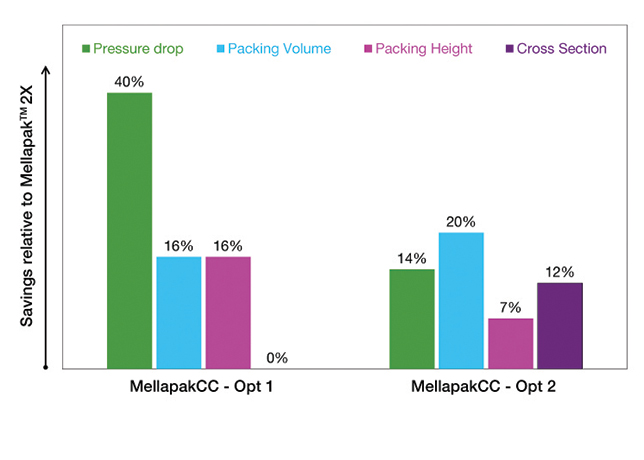 |
Figure 5 ... mellapakCC™ savings relative to Mellapak™2X for two optimisation cases |
In a case study, the CO2 capture efficiency and the hydraulic performance of a MellapakCC™ family member was compared against Mellapak™ 2X.
• The CO2 capture efficiency depends directly on the effective interfacial area generated by the packing at a given liquid load.
A higher effective interfacial area yields higher absorption efficiency. Figure 3 (pilot tests for CO2 absorption from air into NaOH) shows that Sulzer MellapakCC™ provides 17-25 per cent more effective interfacial area than Mellapak™ 2X.
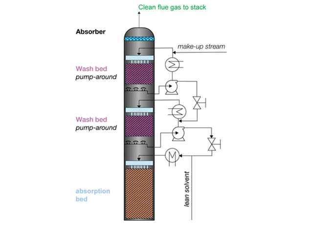 |
Figure 6 ... Absorber - wash section with |
• Pressure drop determines the energy required by the flue gas blower to push gas through the absorber.
A lower pressure drop significantly reduces the blower power consumption and opex.
Figure 4 presents specific pressure drop versus F-Factor (gas load) at various liquid loads.
MellapakCC™ achieves 10-20 per cent lower pressure drop than Mellapak™ 2X across the entire operating range, with the largest savings near capacity limits.
• Lower specific pressure drop directly translates into higher column capacity. MellapakCC™ enables 10-20 per cent higher throughput in the same column cross-section or, alternatively, a reduced absorber diameter for the same duty.
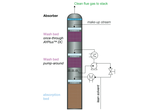 |
Figure 7 ... Absorber pump around and |
Overall, MellapakCC™ excels in all key parameters, including higher capture efficiency , lower specific pressure drop and higher capacity .
This can result in 15-20 per cent less packing volume (Figure 5). For a world-scale carbon capture plant, several thousand cubic meters of packing are saved.
The key benefits include absorber shell capex reduction of 5-10 percent; flue gas blower CAPEX and opex reduction of 5-15 and 10-30 percent, respectively; and lower transportation, steelwork, installation time, and site laydown area requirements.
EMISSION CONTROL
Solvent emissions from the CO2 absorber occur via two mechanisms: Solvent carryover (droplets entrained in the gas) and solvent evaporation (volatile components transferring to the gas phase).
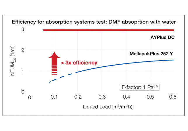 |
Figure 8 ... AYPlus™ versus MellapakPlus™ 252 |
Carry-over is effectively mitigated with advanced mist elimination technologies tailored to the droplet size distribution.
Emissions due to solvent evaporation can be minimised by installing one or two water wash sections above the absorption section in the CO2 absorber.
Conventional pumparound wash beds, historically used to overcome wetting limitations of metal packings at low liquid loads (<1 m³/m²·h) typical of carbon capture (Figure 6), increase liquid recirculation, while reducing the thermodynamic driving force, and thereby limiting the emission control performance.
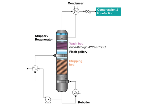 |
Figure 9 ... CO2 stripper column configuration |
The optimal configuration for near-zero solvent emissions (<<1 ppm) is a once-through packed bed fed solely by fresh demineralised water make-up, maximising the driving force (Figure 7).
Sulzer’s AYPlus™ DC hybrid gauze packing eliminates wetting limitations of conventional structured metal sheet packings even at ultra-low liquid loads.
AYPlus™ DC delivers superior, sustained mass transfer efficiency (validated by DMF-water absorption tests directly transferable to amine systems; Figure 8).
The key benefits of the AYPlus™ DC once-through solution include near-zero solvent emissions, ensuring compliance with future regulations, optimum thermodynamics, improved operability and minimal solvent make-up (opex); reduced absorber capex through elimination of a pump, heat exchanger, piping and instrumentation; reducing steelwork and installation time
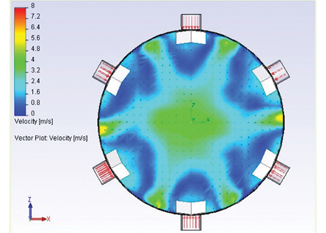 |
Figure 10 ... CFD results showin flow pattern right above reboiler-return nozzles with column diameter of 10 m |
• CO2 stripper: The stripper (regenerator) regenerates the rich solvent into lean solvent by thermally shifting the CO2 equilibrium toward the gas phase, closing the solvent loop (Figure 9).
The regeneration temperature (60-180 deg C) and specific energy duty (typically 2.2-3.5 MJ/kg CO2) are solvent- and technology-dependent, representing the largest opex component.
• Flash gallery and liquid distribution Rich solvent entering the stripper flashes CO2 depending on the temperature and pressure.
Reliable phase disengagement and uniform fluid distribution to the stripping section (liquid loads often >30 cu m/ sq m·h) are critical for the column performance.
Sulzer’s field-proven MellaTech™ technology incorporates customised flash galleries, high-performance inlet devices (e.g. Shell Schoepentoeter™) and mechanically robust designs validated for greenfield and brownfield constraints.
• Stripping section: CO2 desorption occurs across up to three packed beds. Although pressure drop is less critical than in the absorber, MellapakCC™ structured packing remains preferred for its high capacity and reliable heat/mass transfer.
Uniform gas/liquid distribution and hydraulic balancing are achieved using customized column internals.
For large-diameter columns with multiple reboilers, Computational Fluid Dynamics (CFD) modelling (Figure 10) optimises nozzle configuration and the arrangement of the column internals. The integrated MellaTech™ approach ensures reliable, high-performance operation.
• Wash section: Solvent carry-over and vapour emissions must be strictly controlled to meet CO2 product specifications (for example, pipeline or food-grade for beverage industry).
Modern regenerators use packed beds instead of bubble-cap trays due to higher capacity, lower pressure drop and better efficiency. Once-through wash sections clearly outperform pump-around designs.
The condensed water from the overhead CO2 cooler is routed to the wash bed, fully exploiting the superior wetting and transfer characteristics of AYPlus™ DC at minimum liquid loads.
The key benefits of the AYPlus™ DC once-through solution in the regenerator include near-zero solvent emissions into the CO2 product, while meeting the most stringent specifications.
Sulzer’s proprietary technologies - MellapakCC™, AYPlus™ DC, and MellaTech™ - deliver industry-leading CO2 capture efficiency, emission control, and operational reliability.
These innovative solutions significantly lower both capex and opex, enabling cost-effective, large-scale deployment of CC.